
Last Updated on March 6, 2024 by Chuck Wilson
Harley Davidson Golf Cart Wiring continues in this article with the 1967-1978 models.
Harley Davidson golf carts hold a special place in the hearts of enthusiasts and collectors alike. From their humble beginnings to becoming prized possessions, these iconic vehicles have a rich history. However, like any machinery, they require proper maintenance and occasional repairs to keep them running smoothly. One invaluable tool for owners and mechanics is the wiring diagram, especially for models manufactured between 1967 and 1978, known as DE models.
Using The Harley Davidson Golf Cart Wiring Diagrams
Wiring diagrams are intricate maps that depict the electrical circuitry of a vehicle. They serve as a guide for troubleshooting electrical issues, identifying components, and understanding the intricate network of wires. In the case of Harley Davidson golf carts, wiring diagrams are indispensable due to the complexity of their electrical systems.
These diagrams break down the various electrical components and their connections, providing a roadmap for diagnosing and repairing issues. From batteries and chargers to ignition systems and lighting, every aspect of the electrical setup is meticulously documented.
Overview of 1967-1978 DE Models
The period between 1967 and 1978 marked a significant era for Harley Davidson golf carts, particularly with the introduction of the DE models. These carts underwent several advancements and design changes, reflecting the evolving needs and preferences of consumers.
During this time, Harley Davidson experimented with various features and technologies, resulting in improved performance and reliability. Understanding the nuances of these models is crucial for enthusiasts and restorers alike.
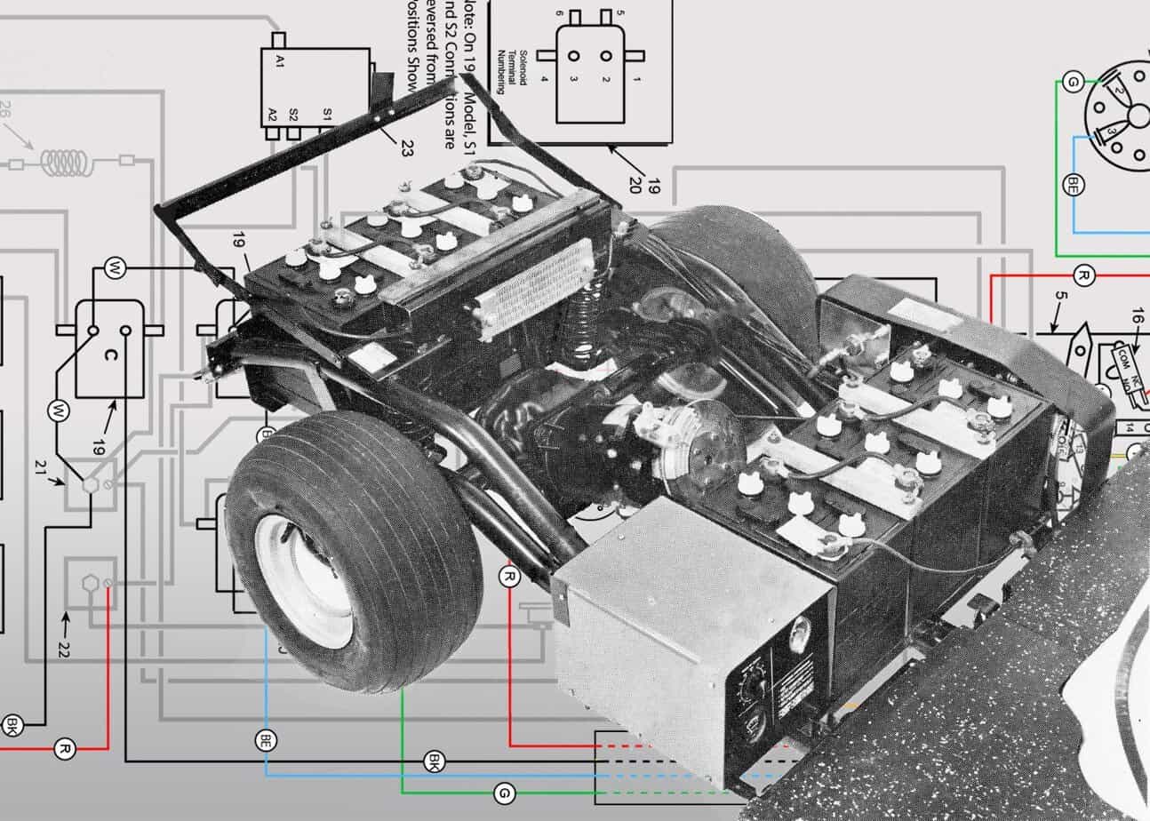
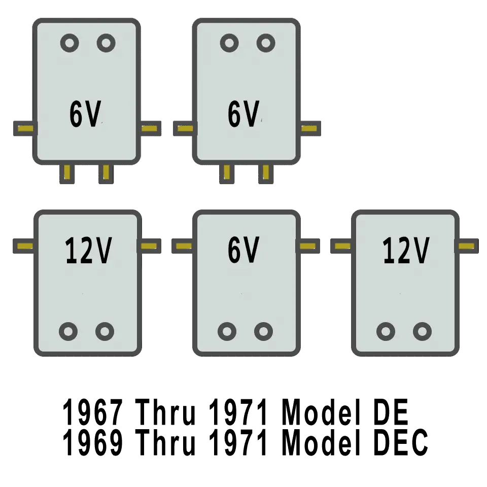
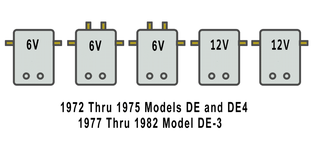
There are five solenoids on the 67-78 instead of the six used in the previous years. The battery arrangement changed as well from the 4 + 2 to the 3 + 3 configuration.
Diagrams
Solenoid Arrangement
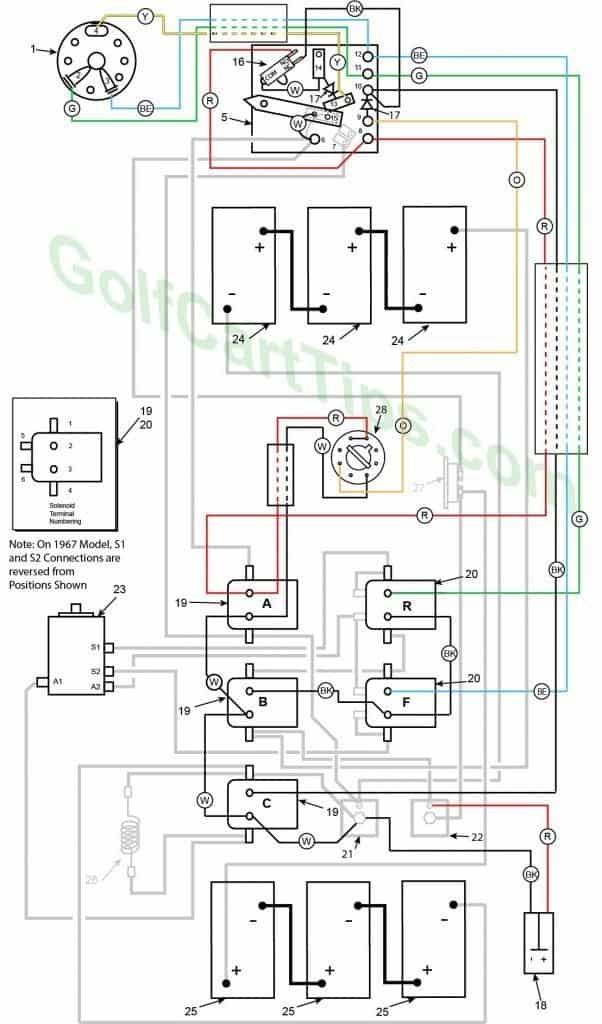
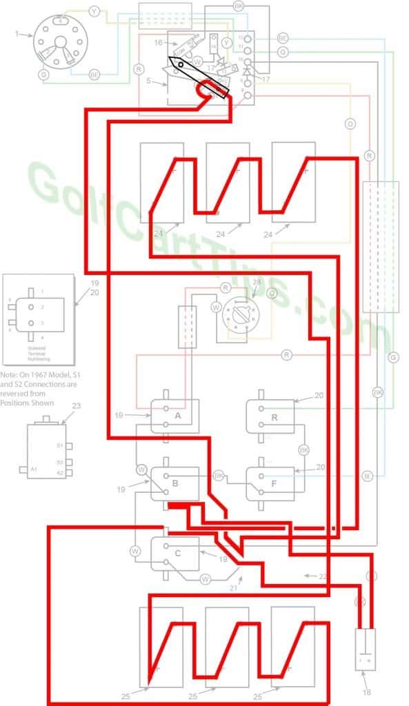
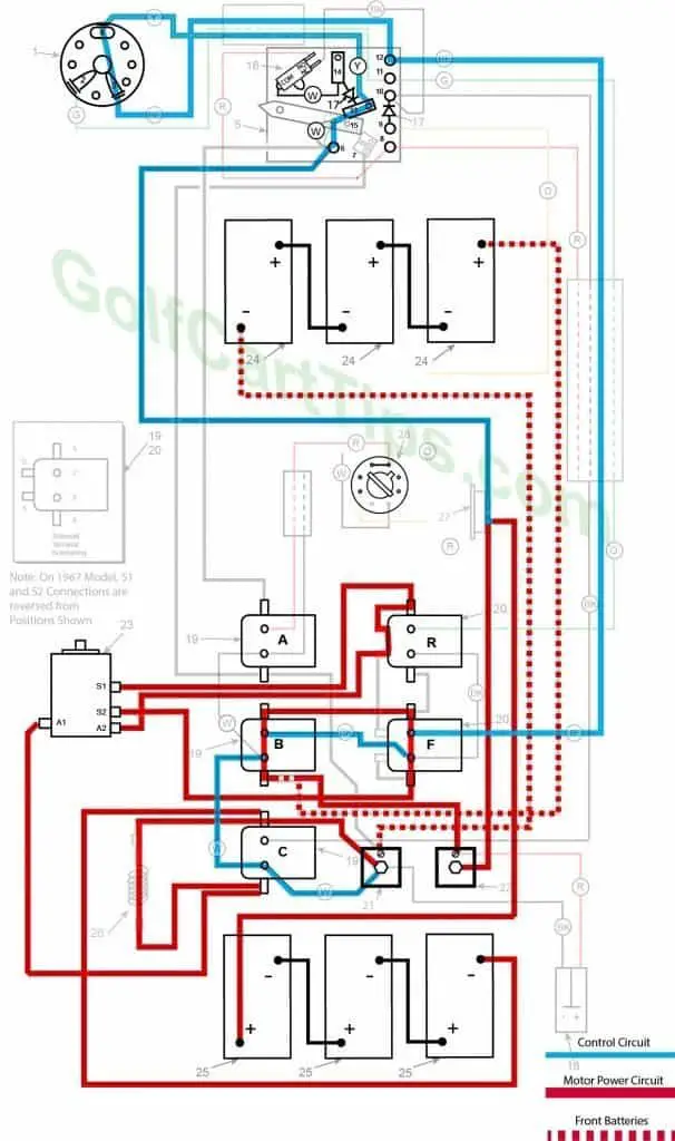
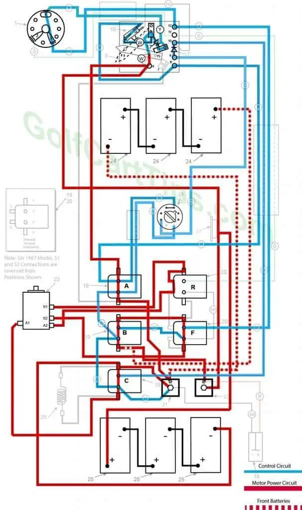
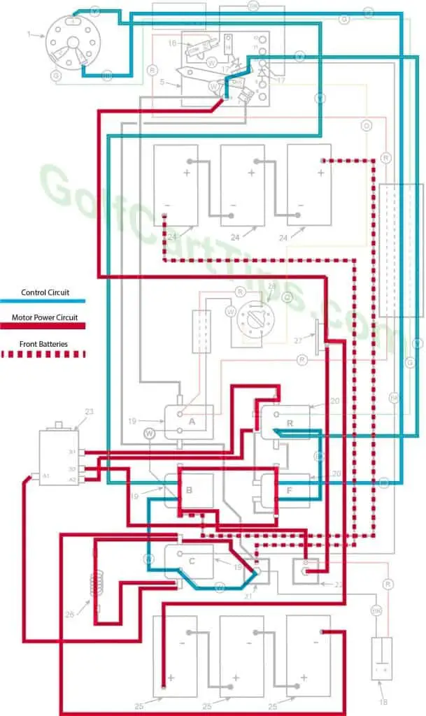
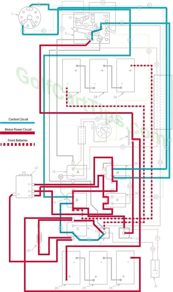
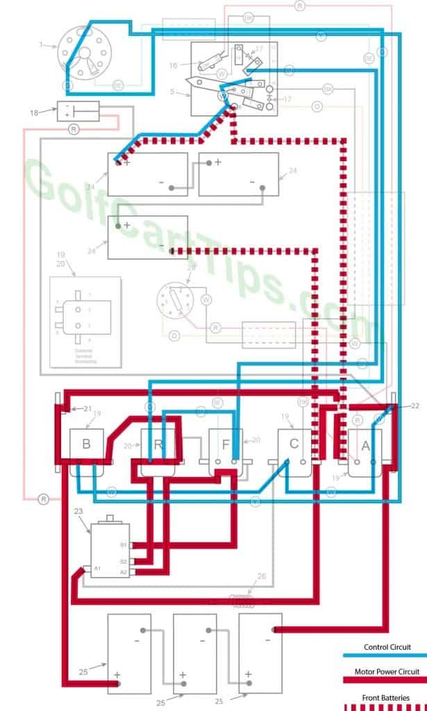
1967-70 Model DE Control Circuit Wiring Diagram for 16 Gauge Wire
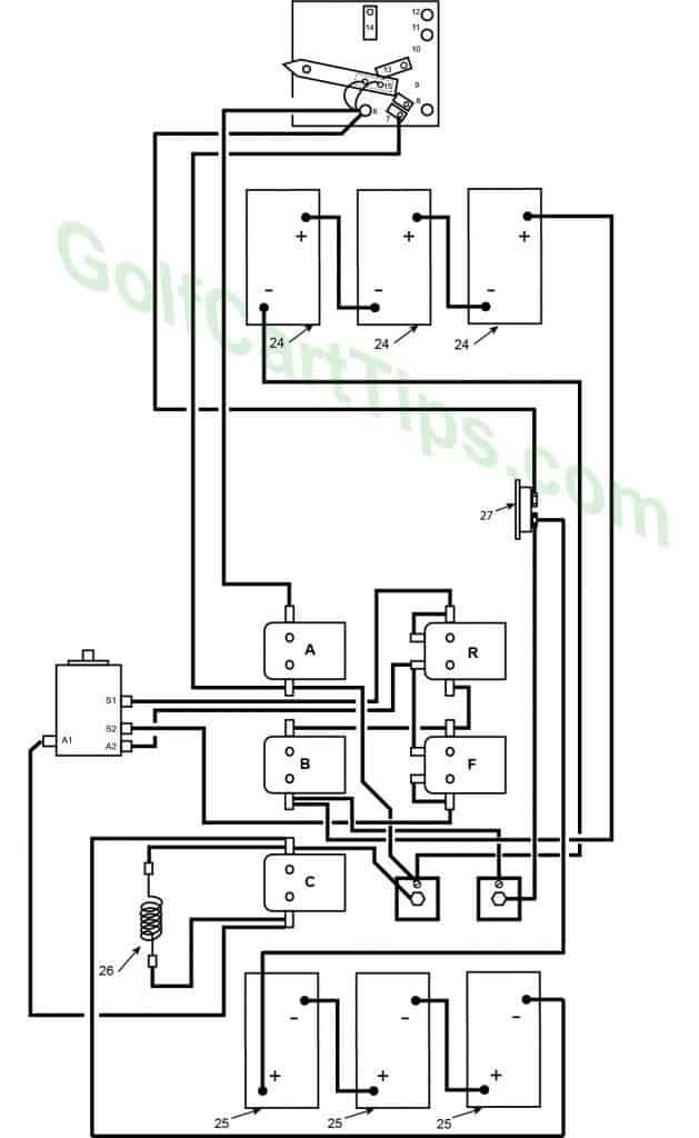
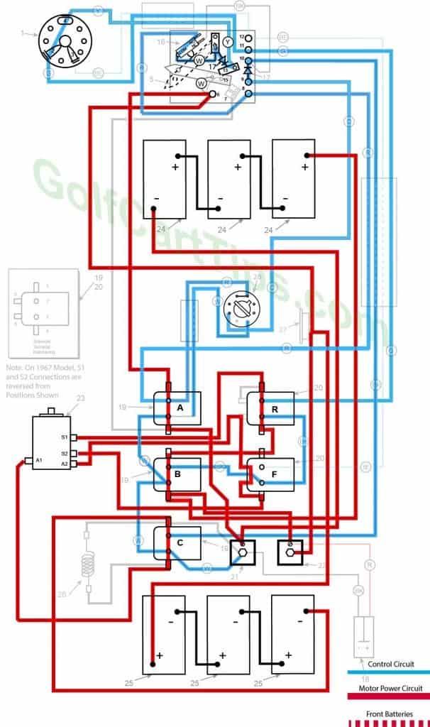
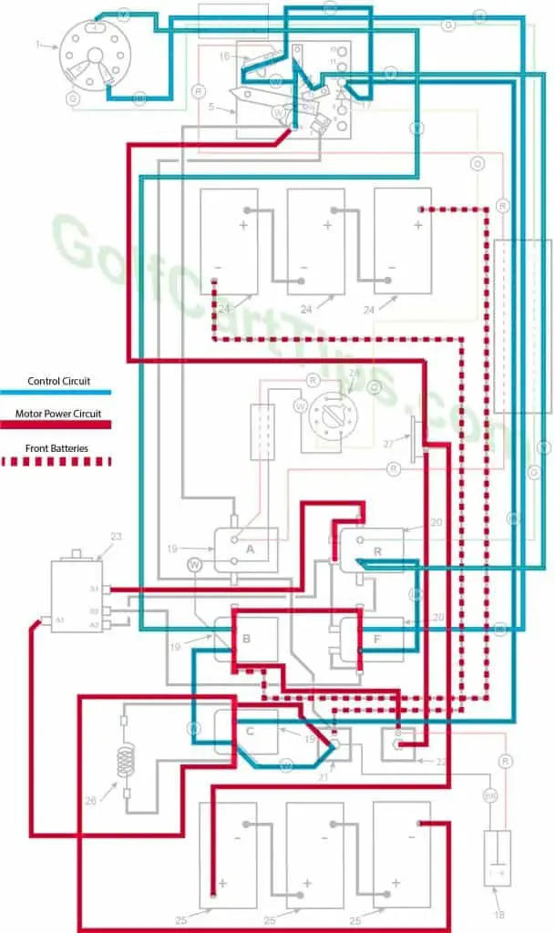
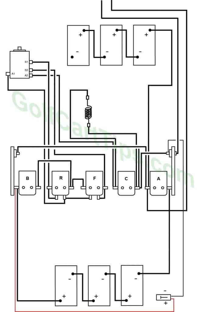
1967-70 Model DE Heavy Cable Diagram
Numbering Key for 1967 -1970 Diagrams
- Key Switch – 3 wires (Green, Blue, Yellow) For terminals 2, 3, and 4
- Key Switch Terminal – Green wire to Speed Switch Connection 11
- Key Switch Terminal – Blue wire to Speed Switch Connection 12
- Key Switch Terminal – Yellow wire to Speed Switch Connection 13
- Speed Switch (Contains Terminals 6, 7, 8, 9, 10, 11,12,13, and 14)
- Speed Switch Terminal – White wire to Terminal 15 on Switch Arm (2), Black wire to Solenoid Terminal A1 and Black wire to Circuit Breaker (4 wires)
- Speed Switch Terminal – Black wire to Solenoid Terminal A4
- Speed Switch Terminal – Red wire to Micro Switch NC Terminal, Red wire to Solenoid Terminal A2
- Speed Switch Terminal – Orange wire to Delay Tube Pin 5
- Speed Switch Terminal – Black wire to Solenoid Terminal C2, Black wire to Micro Switch NC Terminal, Diode to Speed Switch Terminal 9
- Speed Switch Terminal – Green wire to Solenoid Terminal R2, Green wire to Key Switch Terminal 2
- Speed Switch Terminal – Blue wire to Solenoid Terminal F2, Blue wire to Key Switch Terminal 3
- Speed Switch Terminal – Yellow wire to Key Switch Terminal 4
- Speed Switch Terminal – White wire to Micro Switch Common, Diode to Speed Switch Terminal 13
- Speed Switch Arm Terminal – White wire jumper to Speed Switch Terminal 6 (2)
- Micro Switch – Yellow wire to Key Switch Terminal 4 and Red wire to Speed Switch Terminal 6
- Diode
- Charger Connection Plug – Negative Terminal 1 Black wire to Speed Switch Terminal 6 and Positive Terminal 2 Red wire to Motor Terminal A1
- Single Action Solenoid A, B, and C
Solenoid A
A1 – Black wire to Speed Switch Terminal 6
A2 – Red wire to Delay Tube Pin 8, Red wire to Speed Switch Terminal 8
A3 – White wire to Delay Tube Pin 3, White wire to Solenoid Terminal B3
A4 – Black wire to Outer Diode, Black wire to Speed Switch Terminal 7Solenoid B
B1 – Copper Strap to Solenoid Terminal F1
B2 – Black wire to Solenoid Terminal F3
B3 – White wire to Solenoid Terminal A3, White wire to Solenoid Terminal C3
B4 – Black Wire to Inner Diode, Black wire to Front Right Positive Battery TerminalSolenoid C
C1 – Black wire to Resistor 25, Black wire to Right Rear Battery Negative Terminal, Black wire to Outer Diode
C2 – Black wire to Speed Switch Terminal 10
C3 – White wire to Solenoid Terminal B3, White wire to Outer Diode
C4 – Black wire to Resistor 26, Black wire to Motor Terminal A1 - Dual Action Solenoid
Solenoid R
R1 – Black wire to Motor Terminal S1, Copper Strap to R5
R2 – Green wire to Speed Switch Terminal 11
R3 – Black wire to Solenoid Terminal F3
R4 – Copper Strap to Solenoid Terminal F1
R5 – Copper Strap to Solenoid Terminal R1
R6 – Copper Strap to Solenoid Terminal F5, Black wire to Motor Terminal A2Solenoid F
F1 – Copper Strap to Solenoid Terminal R4
F2 – Blue wire to Speed Switch Terminal 12
F3 – Black wire to Solenoid Terminal R3
F4 – Copper Strap to Solenoid Terminal F6, Black wire to Motor Terminal S2 - Outer Diode
- Inner Diode
- Motor
Terminal A1 – Black wire to Solenoid Terminal C4
Terminal A2 – Black wire to Solenoid Terminal R6
Terminal S1 – Black wire to Solenoid Terminal R1
Terminal S2 – Black wire to Solenoid Terminal F4 - Front Batteries
- Rear Batteries
- Resistor
- Circuit Breaker
- Delay Tube
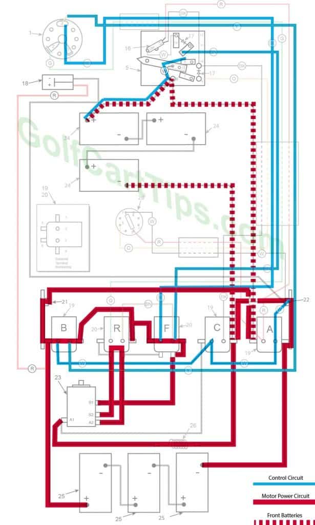
1967-70 Energized Circuits Diagrams
Charging
- Key switch – Off
- Speed Switch – at resting stop
- Solenoid “A” Open – Voltage not applied to small terminals
- Solenoid “B” Open – Voltage not applied to small terminals
- Solenoid “C” Open – Voltage not applied to small terminals
- Solenoid “D” Open – Voltage not applied to small terminals
- Solenoid “E” Open – Voltage not applied to small terminals
- Solenoid “F” Open – Voltage not applied to small terminals
- Voltage to Motor – None
- Voltage across A1 and A2 – None
- Micro Switch – Open
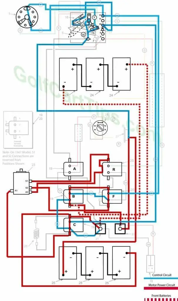
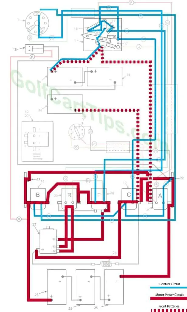
First Speed
- Key switch – Forward
- Speed Switch – Movement toward Second Speed Contact
- Solenoid “A” Closed – Voltage applied to small terminals, continuity across large terminals
- Solenoid “B” Closed – Voltage applied to small terminals, continuity across large terminals
- Solenoid “C” Open – Voltage not applied to small terminals
- Solenoid “D” Open – Voltage not applied to small terminals
- Solenoid “E” Open – Voltage not applied to small terminals
- Solenoid “F” Open – Voltage not applied to small terminals
- Micro Switch – Closed sending voltage to Solenoid “A” and “B” Small Terminals
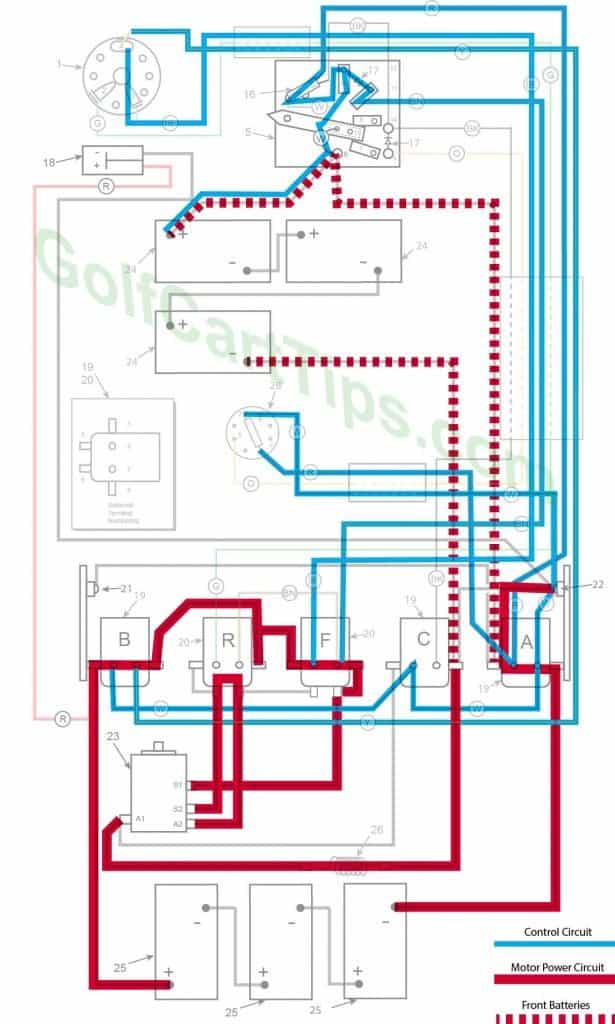
Second Speed
- Key switch – Forward
- Speed Switch – On Second Speed Contact sending voltage to Solenoid “E” small terminals
- Solenoid “A” Closed – Voltage applied to small terminals, continuity across large terminals
- Solenoid “B” Closed – Voltage applied to small terminals, continuity across large terminals
- Solenoid “C” Open – Voltage not applied to small terminals
- Solenoid “D” Open – Voltage not applied to small terminals
- Solenoid “E” Voltage applied to small terminals, continuity across large terminals
- Solenoid “F” Open – Voltage not applied to small terminals
- Micro Switch – Closed sending voltage to Solenoid “A” and “B” Small Terminals
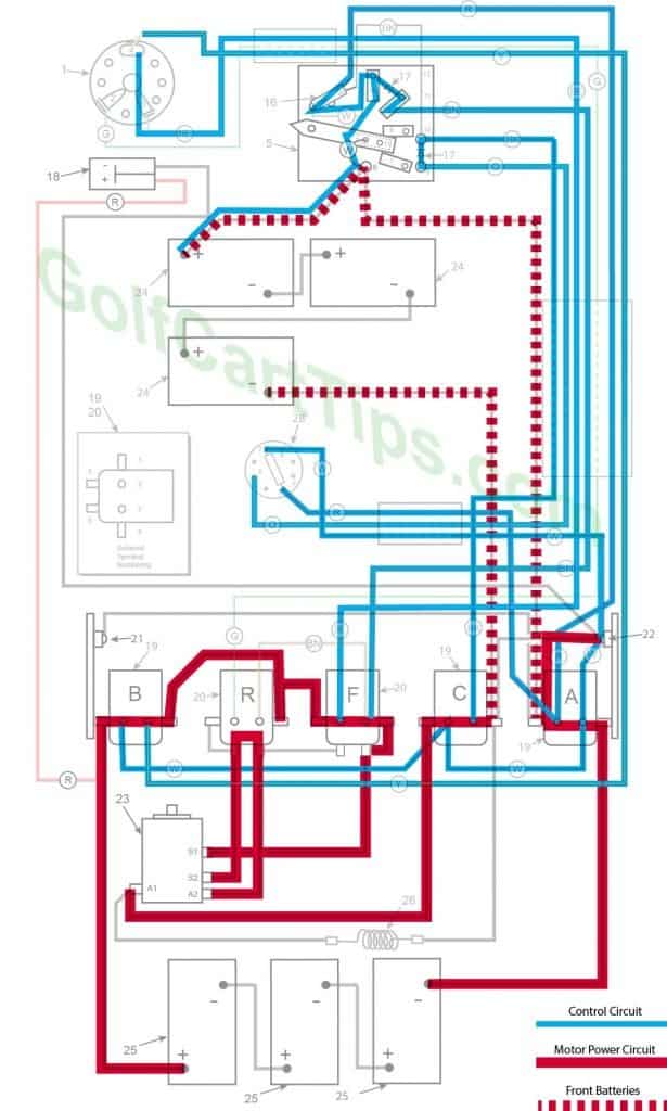
Third Speed
- Key switch – Forward
- Speed Switch – On Third Speed Contact sending voltage to Solenoid “F” small terminals
- Solenoid “A” Closed – Voltage applied to small terminals, continuity across large terminals
- Solenoid “B” Closed – Voltage applied to small terminals, continuity across large terminals
- Solenoid “C” Open – Voltage not applied to small terminals
- Solenoid “D” Open – Voltage not applied to small terminals
- Solenoid “E” Open – Voltage not applied to small terminals
- Solenoid “F” Voltage applied to small terminals, continuity across large terminals
- Micro Switch – Closed sending voltage to Solenoid “A” and “B” Small terminals
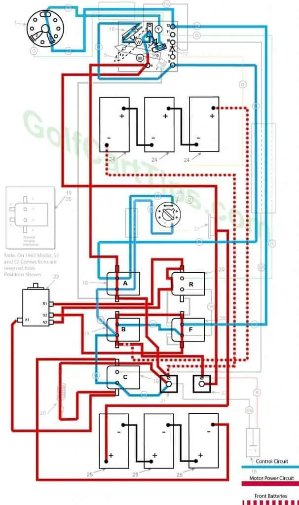
Fourth Speed
- Key switch – Forward
- Speed Switch – Contact #4 Micro Switch has depressed
- Solenoid “A” Closed – Voltage applied to small terminals, continuity across large terminals
- Solenoid “B” Closed – Voltage applied to small terminals, continuity across large terminals
- Solenoid “C” Closed – Voltage applied to small terminals, continuity across large terminals
- Solenoid “F” Closed – Voltage applied to small terminals, continuity across large terminals – Bottom terminals open
- Solenoid “R” Open – Voltage not applied to small terminals – Bottom terminals closed
- Voltage to Motor – 36-volts bypassing the Resistor
- Voltage across A1 and A2 -33.5-volts to 34.5-volts
- Left Motor Diode – Blocking current flowing from Solenoid “A” to Solenoid “C”
- Right Motor Diode – Blocking current flowing from Solenoid “B” to Solenoid “A”
- Speed Switch Diode – Allows current from Speed Switch to third Speed Switch Contact and on to Solenoid “B” and “F”
- Time Delay – Actuated and powering Solenoid “C”
- Micro Switch – Activated and powering Solenoid “A” and Time Delay
Reverse (First Speed Only Shown)
- Key switch – Reverse
- Speed Switch – Same as Forward Speeds
- Solenoid “A” – Same as Forward Speeds
- Solenoid “B” – Same as Forward Speeds
- Solenoid “C” – Same as Forward Speeds
- Solenoid “F” Open – Voltage not applied to small terminals – Bottom terminals closed
- Solenoid “R” Closed – Voltage applied to small terminals, continuity across large terminals – Bottom terminals open
- Voltage to Motor – Same as Forward Speeds
- Voltage across A1 and A2 -Same as Forward Speeds
- Left Motor Diode – Same as Forward Speeds
- Right Motor Diode – Same as Forward Speeds
- Speed Switch Diode – Same as Forward Speeds
- Time Delay – Actuated and powering Solenoid “C”
- Micro Switch – Same as Forward Speeds
- If so equipped – Reverse Buzzer actuated through ACC on Key Switch
1967 Through 1970 Models DE and DEC Troubleshooting Chart
| Symptom | Possible Cause | Remedy |
|---|---|---|
| Batteries will not charge | Accelerator pedal not at rest position and wiper arm is not completely on the first contact block | Refer to Speed Switch Adjustment Section here |
| Corroded or loose battery connections | Check, clean and tighten connections | |
| Faulty Battery | Test each Battery while completely disconnected from the series | |
| Faulty Charger | Use multimeter and test output voltage | |
| Will not go in forward or reverse | Faulty batteries or connections | Inspect batteries and clean connections |
| Faulty key switch | Test key switch with continuity tester | |
| Faulty speed switch | Check speed switch connections | |
| Solenoid "B" not energizing | Check cabling to Solenoid "B" Test solenoid with procedure listed here |
|
| Faulty Motor | Follow Motor trouble shooting procedures | |
| Forward Works, no reverse | Faulty key switch | Test key switch with continuity tester |
| Solenoid "R" not energizing | Check cabling to Solenoid "R" Test solenoid with procedure listed here |
|
| Solenoid "F" open between Large bottom terminals | Check connections to Solenoid "B" large terminals. Test solenoid with procedure listed here |
|
| Reverse works OK, no Forward | Faulty key switch | Test key switch with continuity tester |
| Solenoid "R" open circuit on large bottom terminals | Check connections to Solenoid "R" large terminals. Test solenoid with procedure listed here |
|
| Solenoid "F" not Energizing | Check connections to Solenoid "F" control terminals. Test solenoid with procedure listed here |
|
| Speed 1 Works, no 2, 3, or 4 | Speed Switch wiper arm not making contact with 4th speed contact pad. | Remove and inspect Speed Switch. |
| Speed Switch diode open | Check diode leads. | |
| Speed 1 and 2 Works, no 3, or 4 | Micro switch not making the connection between NC and COM | Test Micro Switch |
| Solenoid "A" not energizing, stuck open | Check connections to Solenoid "A" terminals. Test solenoid with procedure listed here |
|
| Speed 3 and 4 Works, no 1 or 2 | Both Motor diodes open | Check diode condition |
| Solenoid "A" stuck closed | Check connections to Solenoid "A" control terminals. Test solenoid with procedure listed here |
|
| Speed 3 and 4 works, no 1, or 2 | Short in Speed Switch Diode | Inspect, repair, or replace. |
| Speed 2 and 4 works, no 1 or 3 | Solenoid "C" stuck closed bypassing Resistor | Test solenoid "C" with procedure listed here |
| Open Resistor | Check Resistor connections. | |
| Speed 1 and 3 works, no 2 or 4 | Solenoid "C" not energizing or stuck open passing all current through Resistor | Test solenoid "C" with procedure listed here |
| Speed 1 and 4 works, no 2 or 3 | Time Delay Tube shorted | Check Time Delay Tube connections. |
| Speed 1, 2, and 3 works, no 4 | Time Delay Tube open or faulty | Check Time Delay Tube connections. |
| Speed 3 has a long delay or too short of a delay | Time Delay Tube open faulty | Test Time Delay Tube. |
| Front set of batteries goes dead or Rear set of batteries goes dead | One Motor Diode is open | Check connections to Motor Diode or replace. |
Wiring Diagrams For 1971 DE
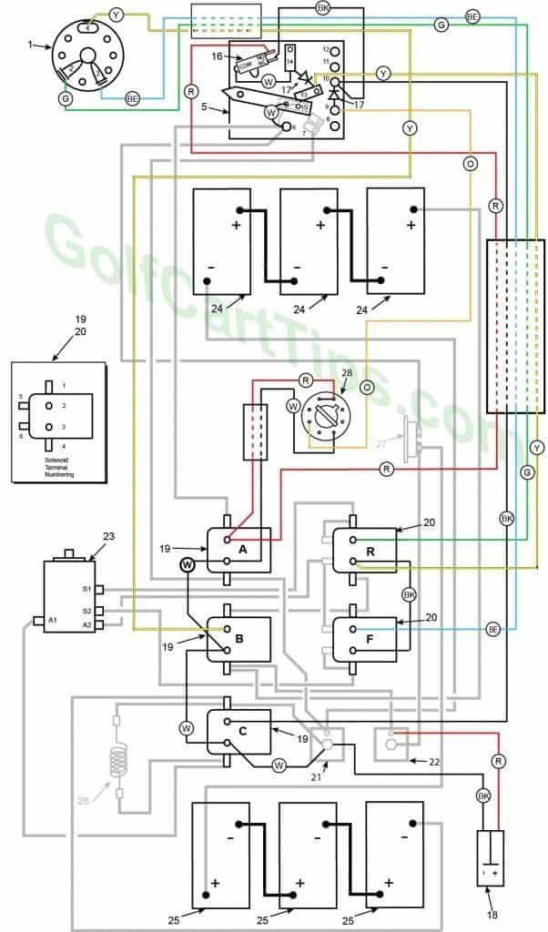
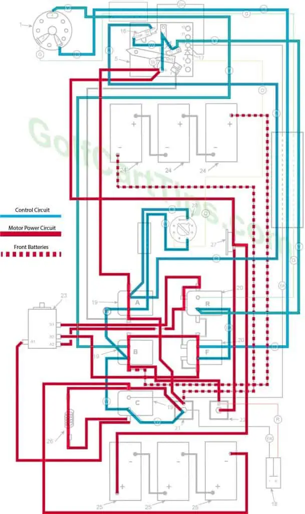
1971 Model DE Control Circuit Wiring Diagram for 16 Gauge Wire
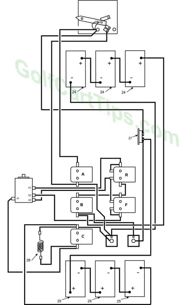
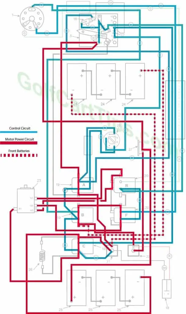
1971 Model DE Heavy Cable Diagram
Charging
- Key switch – Off
- Speed Switch – at resting stop
- Solenoid “A” Open – Voltage not applied to small terminals
- Solenoid “B” Open – Voltage not applied to small terminals
- Solenoid “C” Open – Voltage not applied to small terminals
- Solenoid “F” Open – Voltage not applied to small terminals – Bottom terminals closed
- Solenoid “R” Open – Voltage not applied to small terminals – Bottom terminals closed
- Voltage to Motor – None
- Voltage across A1 and A2 – None
- Motor Diodes – None
- Speed Switch Diode – None
- Time Delay – Open
- Micro Switch – NO Open NC Closed
First Speed
- Key switch – Forward
- Speed Switch – Contact #3
- Solenoid “A” Open – Voltage not applied to small terminals
- Solenoid “B” Closed – Voltage applied to small terminals, continuity across large terminals
- Solenoid “C” Open – Voltage not applied to small terminals
- Solenoid “F” Closed – Voltage applied to small terminals, continuity across large terminals – Bottom terminals open
- Solenoid “R” Open – Voltage not applied to small terminals – Bottom terminals closed
- Voltage to Motor – 18-volts through the Resistor
- Voltage across A1 and A2 – 12-volts
- Left Motor Diode – Current flowing from Solenoid “A” to Solenoid “B”
- Right Motor Diode – Current flowing from Solenoid “C” to Solenoid “A”
- Speed Switch Diode – Blocks current from Speed Switch fourth Contact
- Time Delay – Open
- Micro Switch – Open
Second Speed
- Key switch – Forward
- Speed Switch – Contact #4 Micro Switch not depressed yet
- Solenoid “A” Open – Voltage not applied to small terminals
- Solenoid “B” Closed – Voltage applied to small terminals, continuity across large terminals
- Solenoid “C” Closed – Voltage applied to small terminals, continuity across large terminals
- Solenoid “F” Closed – Voltage applied to small terminals, continuity across large terminals – Bottom terminals open
- Solenoid “R” Open – Voltage not applied to small terminals – Bottom terminals closed
- Voltage to Motor – 18-volts bypassing the Resistor
- Voltage across A1 and A2 – 15.5-volts to 16.5-volts
- Left Motor Diode – Current flowing from Solenoid “A” to Solenoid “B”
- Right Motor Diode – Current flowing from Solenoid “C” to Solenoid “A”
- Speed Switch Diode – Allows current from Speed Switch to third Speed Switch Contact and on to Solenoid “B” and “F”
- Time Delay – Open
- Micro Switch – not activated but allowing current to pass to power Solenoid “C”
Third Speed
- Key switch – Forward
- Speed Switch – Contact #4 Micro Switch has depressed
- Solenoid “A” Closed – Voltage applied to small terminals, continuity across large terminals
- Solenoid “B” Closed – Voltage applied to small terminals, continuity across large terminals
- Solenoid “C” Open – Voltage not applied to small terminals
- Solenoid “F” Closed – Voltage applied to small terminals, continuity across large terminals – Bottom terminals open
- Solenoid “R” Open – Voltage not applied to small terminals – Bottom terminals closed
- Voltage to Motor – 36-volts through the Resistor
- Voltage across A1 and A2 -30.5-volts to 31.5-volts
- Left Motor Diode – Blocking current flowing from Solenoid “A” to Solenoid “C”
- Right Motor Diode – Blocking current flowing from Solenoid “B” to Solenoid “A”
- Speed Switch Diode – Allows current from Speed Switch to third Speed Switch Contact and on to Solenoid “B” and “F”
- Time Delay – Actuated and powering Solenoid “C” after 1.8 seconds
- Micro Switch – Activated and powering Solenoid “A” and Time Delay
Fourth Speed
- Key switch – Forward
- Speed Switch – Contact #4 Micro Switch has depressed
- Solenoid “A” Closed – Voltage applied to small terminals, continuity across large terminals
- Solenoid “B” Closed – Voltage applied to small terminals, continuity across large terminals
- Solenoid “C” Closed – Voltage applied to small terminals, continuity across large terminals
- Solenoid “F” Closed – Voltage applied to small terminals, continuity across large terminals – Bottom terminals open
- Solenoid “R” Open – Voltage not applied to small terminals – Bottom terminals closed
- Voltage to Motor – 36-volts bypassing the Resistor
- Voltage across A1 and A2 -33.5-volts to 34.5-volts
- Left Motor Diode – Blocking current flowing from Solenoid “A” to Solenoid “C”
- Right Motor Diode – Blocking current flowing from Solenoid “B” to Solenoid “A”
- Speed Switch Diode – Allows current from Speed Switch to third Speed Switch Contact and on to Solenoid “B” and “F”
- Time Delay – Actuated and powering Solenoid “C”
- Micro Switch – Activated and powering Solenoid “A” and Time Delay
Reverse (First Speed Only Shown)
- Key switch – Reverse
- Speed Switch – Same as Forward Speeds
- Solenoid “A” – Same as Forward Speeds
- Solenoid “B” – Same as Forward Speeds
- Solenoid “C” – Same as Forward Speeds
- Solenoid “F” Open – Voltage not applied to small terminals – Bottom terminals closed
- Solenoid “R” Closed – Voltage applied to small terminals, continuity across large terminals – Bottom terminals open
- Voltage to Motor – Same as Forward Speeds
- Voltage across A1 and A2 -Same as Forward Speeds
- Left Motor Diode – Same as Forward Speeds
- Right Motor Diode – Same as Forward Speeds
- Speed Switch Diode – Same as Forward Speeds
- Time Delay – Actuated and powering Solenoid “C”
- Micro Switch – Same as Forward Speeds
- If so equipped – Reverse Buzzer actuated through ACC on Key Switch
Numbering Key For 1971 Diagrams
- Key Switch – 3 wires (Green, Blue, Yellow) For terminals 2, 3, and 4
- Key Switch Terminal – Green wire to Speed Switch Connection 11
- Key Switch Terminal – Blue wire to Speed Switch Connection 12
- Key Switch Terminal – Yellow wire to Speed Switch Connection 13
- Speed Switch (Contains Terminals 6, 7, 8, 9, 10, 11,12,13, and 14)
- Speed Switch Terminal – White wire to Terminal 15 on Switch Arm (2), Black wire to Solenoid Terminal A1 and Black wire to Circuit Breaker (4 wires)
- Speed Switch Terminal – Black wire to Solenoid Terminal A4
- Speed Switch Terminal – Red wire to Micro Switch NC Terminal, Red wire to Solenoid Terminal A2
- Speed Switch Terminal – Orange wire to Delay Tube Pin 5
- Speed Switch Terminal – Black wire to Solenoid Terminal C2, Black wire to Micro Switch NC Terminal, Diode to Speed Switch Terminal 9
- Speed Switch Terminal – Green wire to Solenoid Terminal R2, Green wire to Key Switch Terminal 2
- Speed Switch Terminal – Blue wire to Solenoid Terminal F2, Blue wire to Key Switch Terminal 3
- Speed Switch Terminal – Yellow wire to Key Switch Terminal 4
- Speed Switch Terminal – White wire to Micro Switch Common, Diode to Speed Switch Terminal 13
- Speed Switch Arm Terminal – White wire jumper to Speed Switch Terminal 6 (2)
- Micro Switch – Yellow wire to Key Switch Terminal 4 and Red wire to Speed Switch Terminal 6
- Diode
- Charger Connection Plug – Negative Terminal 1 Black wire to Speed Switch Terminal 6 and Positive Terminal 2 Red wire to Motor Terminal A1
- Single Action Solenoid A,B, and C
Solenoid A
A1 – Black wire to Speed Switch Terminal 6
A2 – Red wire to Delay Tube Pin 8, Red wire to Speed Switch Terminal 8
A3 – White wire to0 Delay Tube Pin 3, White wire to Solenoid Terminal B3
A4 – Black wire to Outer Diode, Black wire to Speed Switch Terminal 7Solenoid B
B1 – Copper Strap to Solenoid Terminal F1
B2 – Black wire to Solenoid Terminal F3
B3 – White wire to Solenoid Terminal A3, White wire to Solenoid Terminal C3
B4 – Black Wire to Inner Diode, Black wire to Front Right Positive Battery TerminalSolenoid C
C1 – Black wire to Resistor 25, Black wire to Right Rear Battery Negative Terminal, Black wire to Outer Diode
C2 – Black wire to Speed Switch Terminal 10
C3 – White wire to Solenoid Terminal B3, White wire to Outer Diode
C4 – Black wire to Resistor 26, Black wire to Motor Terminal A1 - Dual Action Solenoid
Solenoid R
R1 – Black wire to Motor Terminal S1, Copper Strap to R5
R2 – Green wire to Speed Switch Terminal 11
R3 – Black wire to Solenoid Terminal F3
R4 – Copper Strap to Solenoid Terminal F1
R5 – Copper Strap to Solenoid Terminal R1
R6 – Copper Strap to Solenoid Terminal F5, Black wire to Motor Terminal A2Solenoid F
F1 – Copper Strap to Solenoid Terminal R4
F2 – Blue wire to Speed Switch Terminal 12
F3 – Black wire to Solenoid Terminal R3
F4 – Copper Strap to Solenoid Terminal F6, Black wire to Motor Terminal S2 - Outer Diode
- Inner Diode
- Motor
Terminal A1 – Black wire to Solenoid Terminal C4
Terminal A2 – Black wire to Solenoid Terminal R6
Terminal S1 – Black wire to Solenoid Terminal R1
Terminal S2 – Black wire to Solenoid Terminal F4 - Front Batteries
- Rear Batteries
- Resistor
- Circuit Breaker
- Delay Tube
Wiring Diagrams For 1972 to 1975 DE
Overview
The DE3 circuitry uses a battery switching system and resistor to control current flow to the traction motor.
There are two basic circuits involved:
Solenoid 18-volt control circuit-Key Switch, Time Delay Tube, and Solenoids.
Traction Motor 18-36-volt Circuit: Uses Solenoid contacts, Resistor, Diodes, and Traction Motor.
Solenoid “A” is used in this circuit to switch from 18-volts parallel to 36-volts series. “F” and “R” are used to control forward and reverse, and Solenoid “C” is used to pass through the Resistor, or to bypass it (i.e. first and third speeds). Therefore the resistor/voltage combinations are as follows:
First Speed – 18-volts passing through the Resistor
Second Speed 18-volts bypassing the Resistor
Third Speed 36-volts passing through the Resistor
Fourth Speed 36-volts bypassing the Resistor
Following the wiring diagrams, this is the description of what state each component is in during the different stages between charging and fourth speed:
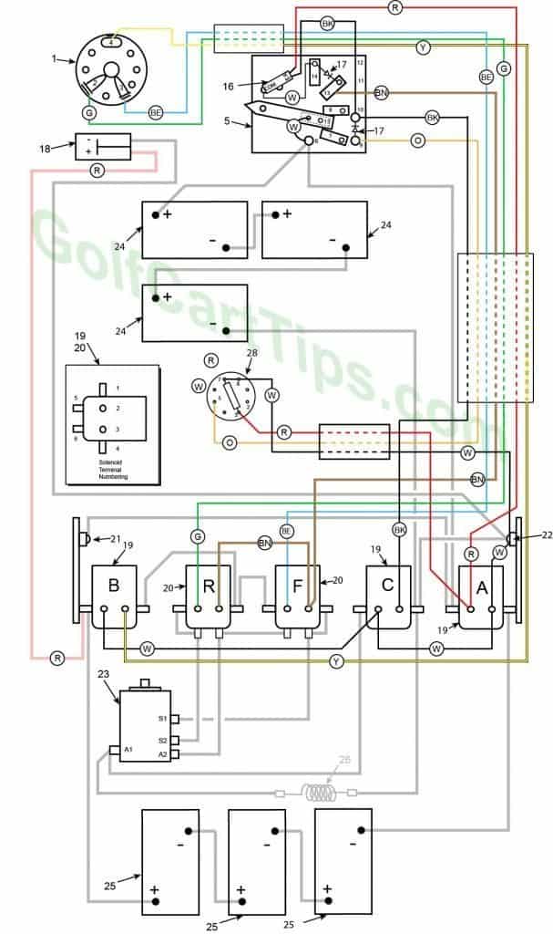
1972 to 1975 Model DE Control Circuit Wiring Diagram for 16 Gauge Wire
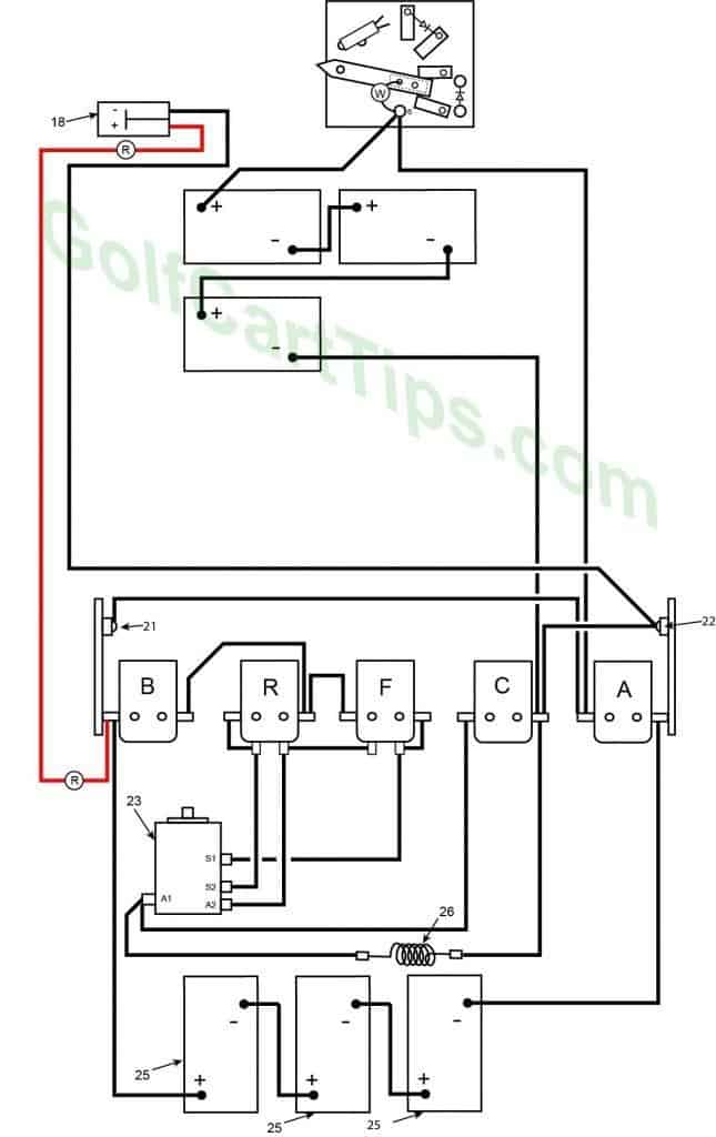
1972 to 1975 Model DE Heavy Cable Diagram
Charging
- Key switch – Off
- Speed Switch – at resting stop
- Solenoid “A” Open – Voltage not applied to small terminals
- Solenoid “B” Open – Voltage not applied to small terminals
- Solenoid “C” Open – Voltage not applied to small terminals
- Solenoid “F” Open – Voltage not applied to small terminals – Bottom terminals closed
- Solenoid “R” Open – Voltage not applied to small terminals – Bottom terminals closed
- Voltage to Motor – None
- Voltage across A1 and A2 – None
- Motor Diodes – None
- Speed Switch Diode – None
- Time Delay – Open
- Micro Switch – Open
First Speed
- Key switch – Forward
- Speed Switch – Contact #3
- Solenoid “A” Open – Voltage not applied to small terminals
- Solenoid “B” Closed – Voltage applied to small terminals, continuity across large terminals
- Solenoid “C” Open – Voltage not applied to small terminals
- Solenoid “F” Closed – Voltage applied to small terminals, continuity across large terminals – Bottom terminals open
- Solenoid “R” Open – Voltage not applied to small terminals – Bottom terminals closed
- Voltage to Motor – 18-volts through the Resistor
- Voltage across A1 and A2 – 12-volts
- Left Motor Diode – Current flowing from Solenoid “A” to Solenoid “B”
- Right Motor Diode – Current flowing from Solenoid “C” to Solenoid “A”
- Speed Switch Diode – Blocks current from Speed Switch fourth Contact
- Time Delay – Open
- Micro Switch – Open
Second Speed
- Key switch – Forward
- Speed Switch – Contact #4 Micro Switch not depressed yet
- Solenoid “A” Open – Voltage not applied to small terminals
- Solenoid “B” Closed – Voltage applied to small terminals, continuity across large terminals
- Solenoid “C” Closed – Voltage applied to small terminals, continuity across large terminals
- Solenoid “F” Closed – Voltage applied to small terminals, continuity across large terminals – Bottom terminals open
- Solenoid “R” Open – Voltage not applied to small terminals – Bottom terminals closed
- Voltage to Motor – 18-volts bypassing the Resistor
- Voltage across A1 and A2 – 15.5-volts to 16.5-volts
- Left Motor Diode – Current flowing from Solenoid “A” to Solenoid “B”
- Right Motor Diode – Current flowing from Solenoid “C” to Solenoid “A”
- Speed Switch Diode – Allows current from Speed Switch to third Speed Switch Contact and on to Solenoid “B” and “F”
- Time Delay – Open
- Micro Switch – not activated but allowing current to pass to power Solenoid “C”
Third Speed
- Key switch – Forward
- Speed Switch – Contact #4 Micro Switch has depressed
- Solenoid “A” Closed – Voltage applied to small terminals, continuity across large terminals
- Solenoid “B” Closed – Voltage applied to small terminals, continuity across large terminals
- Solenoid “C” Open – Voltage not applied to small terminals
- Solenoid “F” Closed – Voltage applied to small terminals, continuity across large terminals – Bottom terminals open
- Solenoid “R” Open – Voltage not applied to small terminals – Bottom terminals closed
- Voltage to Motor – 36-volts through the Resistor
- Voltage across A1 and A2 -30.5-volts to 31.5-volts
- Left Motor Diode – Blocking current flowing from Solenoid “A” to Solenoid “C”
- Right Motor Diode – Blocking current flowing from Solenoid “B” to Solenoid “A”
- Speed Switch Diode – Allows current from Speed Switch to third Speed Switch Contact and on to Solenoid “B” and “F”
- Time Delay – Actuated and powering Solenoid “C” after 1.8 seconds
- Micro Switch – Activated and powering Solenoid “A” and Time Delay
Fourth Speed
- Key switch – Forward
- Speed Switch – Contact #4 Micro Switch has depressed
- Solenoid “A” Closed – Voltage applied to small terminals, continuity across large terminals
- Solenoid “B” Closed – Voltage applied to small terminals, continuity across large terminals
- Solenoid “C” Closed – Voltage applied to small terminals, continuity across large terminals
- Solenoid “F” Closed – Voltage applied to small terminals, continuity across large terminals – Bottom terminals open
- Solenoid “R” Open – Voltage not applied to small terminals – Bottom terminals closed
- Voltage to Motor – 36-volts bypassing the Resistor
- Voltage across A1 and A2 -33.5-volts to 34.5-volts
- Left Motor Diode – Blocking current flowing from Solenoid “A” to Solenoid “C”
- Right Motor Diode – Blocking current flowing from Solenoid “B” to Solenoid “A”
- Speed Switch Diode – Allows current from Speed Switch to third Speed Switch Contact and on to Solenoid “B” and “F”
- Time Delay – Actuated and powering Solenoid “C”
- Micro Switch – Activated and powering Solenoid “A” and Time Delay
Reverse (First Speed Only Shown)
- Key switch – Reverse
- Speed Switch – Same as Forward Speeds
- Solenoid “A” – Same as Forward Speeds
- Solenoid “B” – Same as Forward Speeds
- Solenoid “C” – Same as Forward Speeds
- Solenoid “F” Open – Voltage not applied to small terminals – Bottom terminals closed
- Solenoid “R” Closed – Voltage applied to small terminals, continuity across large terminals – Bottom terminals open
- Voltage to Motor – Same as Forward Speeds
- Voltage across A1 and A2 -Same as Forward Speeds
- Left Motor Diode – Same as Forward Speeds
- Right Motor Diode – Same as Forward Speeds
- Speed Switch Diode – Same as Forward Speeds
- Time Delay – Actuated and powering Solenoid “C”
- Micro Switch – Same as Forward Speeds
- If so equipped – Reverse Buzzer actuated through ACC on Key Switch
Numbering Key for 1972 and Up Diagrams
- Key Switch – 3 wires (Green, Blue, Yellow) For terminals 2, 3, and 4
- Key Switch Terminal – Green wire to Speed Switch Connection 11
- Key Switch Terminal – Blue wire to Speed Switch Connection 12
- Key Switch Terminal – Yellow wire to Speed Switch Connection 13
- Speed Switch (Contains Terminals 6, 7, 8, 9, 10, 11,12,13, and 14)
- Speed Switch Terminal – White wire to Terminal 15 on Switch Arm (2), Black wire to Solenoid Terminal A1 and Black wire to Front Battery Positive Terminal
- Not Used
- Not Used
- Speed Switch Terminal – Orange wire to Delay Tube Pin 5, Diode to Speed Switch Terminal 10
- Speed Switch Terminal – Black wire to Solenoid Terminal C3, Black wire to Micro Switch NC Terminal, Diode to Speed Switch Terminal 9
- Not Used
- Not Used
- Speed Switch Terminal – Brown wire to Solenoid Terminal F3, Diode to Speed Switch Terminal 14
- Speed Switch Terminal – White wire to Micro Switch Common, Diode to Speed Switch Terminal 13
- Speed Switch Arm Terminal – White wire jumper to Speed Switch Terminal 6 (2)
- Micro Switch – White wire from Com to Speed Switch Terminal 14, Red wire from NO to Solenoid Terminal A2, and Black wire from NC to Speed Switch Terminal 10
- Diode (2)
- Charger Connection Plug – Negative Terminal 1 Black wire to Right Diode 22 and Positive Terminal 2 Red wire to Solenoid Terminal B1
- Single Action Solenoid A,B, and C
Solenoid A
A1 – Black wire to Speed Switch Terminal 6, Black wire to Left Diode 21
A2 – Red wire to Delay Tube Pin 8, Red wire to Speed Switch Terminal 3 and Red wire to Micro Switch NC
A3 – White wire to Delay Tube Pin 3, White wire to Solenoid Terminal C2
A4 – Black wire to Rear Battery Negative TerminalSolenoid B
B1 – Black wire to Rear Battery Positive Termina and Red wire to Charger Connection Plug Terminal 2
B2 – White wire to Solenoid Terminal C2
B3 – Yellow wire to Key Switch Terminal 4
B4 – Copper Strap to Solenoid Terminal R4Solenoid C
C1 – Black wire to Motor Terminal A1
C2 – White wire to Solenoid Terminal B2 and White wire to Solenoid Terminal A3
C3 – Black wire to Speed Switch Terminal 10
C4 – Copper Strap to Right Diode 22, Black wire to Resistor 26, Black wire to Front Battery Negative Terminal - Dual Action Solenoid
Solenoid R
R1 – Copper Strap to R5
R2 – Green wire to Key Switch Terminal 2
R3 – Brown wire to Solenoid Terminal F3
R4 – Copper Strap to Solenoid Terminal B4 and Copper Strap to Solenoid Terminal F1
R5 – Copper Strap to Solenoid Terminal R1, Black wire to Motor Terminal S2
R6 – Copper Strap to Solenoid Terminal F5, Black wire to Motor Terminal A2Solenoid F
F1 – Copper Strap to Solenoid Terminal R4
F2 – Blue wire to Key Switch Terminal 3
F3 – Brown wire to Solenoid Terminal R3 and Brown wire to Speed Switch Terminal 13
F4 – Copper Strap to Solenoid Terminal F6, Black wire to Motor Terminal S1 - Left Diode
- Right Diode
- Motor
Terminal A1 – Black wire to Resistor 26 and Solenoid Terminal C1
Terminal A2 – Black wire to Solenoid Terminal R6
Terminal S1 – Black wire to Solenoid Terminal F6
Terminal S2 – Black wire to Solenoid Terminal R5 - Front Batteries
- Rear Batteries
- Resistor
- Not Used
- Delay Tube
Wiring Diagrams For 1976 to 1978 DE
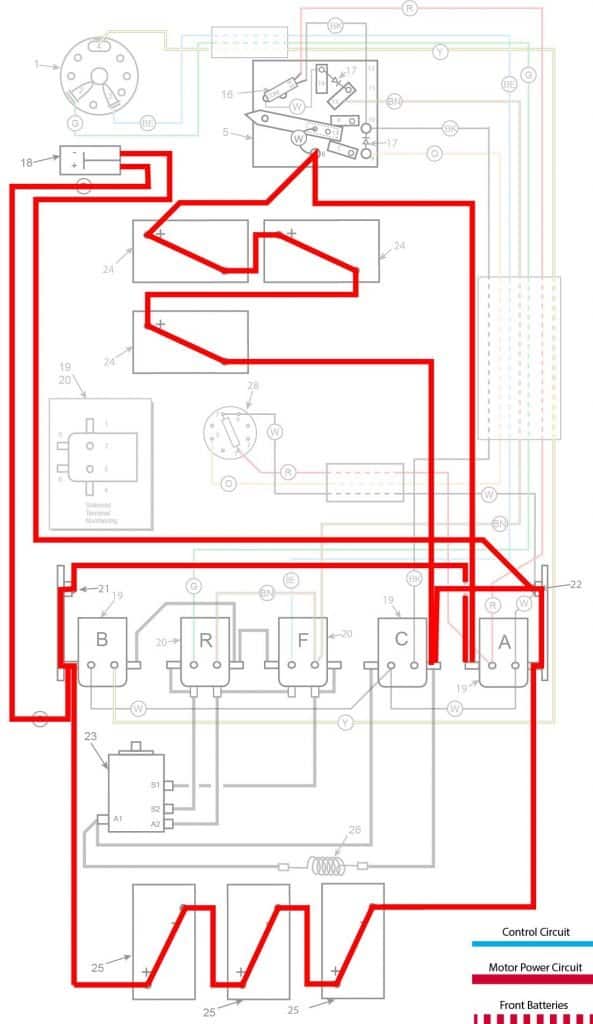
The 1976 to 1978 Models are different from the 1975 models in that the front batteries are changed in orientation, as shown below. Wiring is essentially the same until 1979.
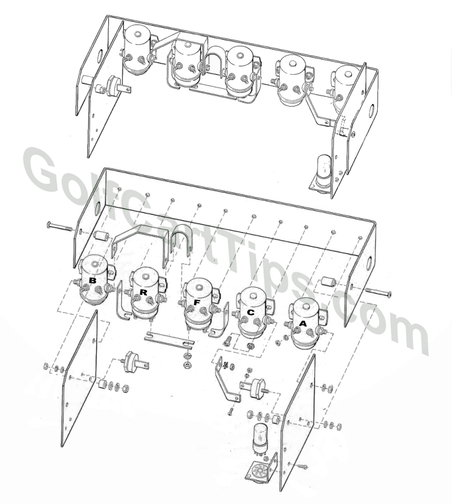
Solenoid Array Exploded View
Speed Switch – Exploded View
Troubleshooting Chart for 1971 To 1978 Model DE
| Symptom | Possible Cause | Remedy |
|---|---|---|
| Batteries will not charge | Accelerator pedal not at rest position and wiper arm is not completely on the first contact block | Refer to Speed Switch Adjustment Section here |
| Corroded or loose battery connections | Check, clean and tighten connections | |
| Faulty Battery | Test each Battery while completely disconnected from the series | |
| Faulty Charger | Use multimeter and test output voltage | |
| Will not go in forward or reverse | Faulty batteries or connections | Inspect batteries and clean connections |
| Faulty key switch | Test key switch with continuity tester | |
| Faulty speed switch | Check speed switch connections | |
| Solenoid "B" not energizing | Check cabling to Solenoid "B" Test solenoid with procedure listed here |
|
| Faulty Motor | Follow Motor trouble shooting procedures | |
| Forward Works, no reverse | Faulty key switch | Test key switch with continuity tester |
| Solenoid "R" not energizing | Check cabling to Solenoid "R" Test solenoid with procedure listed here |
|
| Solenoid "F" open between Large bottom terminals | Check connections to Solenoid "B" large terminals. Test solenoid with procedure listed here |
|
| Reverse works OK, no Forward | Faulty key switch | Test key switch with continuity tester |
| Solenoid "R" open circuit on large bottom terminals | Check connections to Solenoid "R" large terminals. Test solenoid with procedure listed here |
|
| Solenoid "F" not Energizing | Check connections to Solenoid "F" control terminals. Test solenoid with procedure listed here |
|
| Speed 1 Works, no 2, 3, or 4 | Speed Switch wiper arm not making contact with 4th speed contact pad. | Remove and inspect Speed Switch. |
| Speed Switch diode open | Check diode leads. | |
| Speed 1 and 2 Works, no 3, or 4 | Micro switch not making the connection between NC and COM | Test Micro Switch |
| Solenoid "A" not energizing, stuck open | Check connections to Solenoid "A" terminals. Test solenoid with procedure listed here |
|
| Speed 3 and 4 Works, no 1 or 2 | Both Motor diodes open | Check diode condition |
| Solenoid "A" stuck closed | Check connections to Solenoid "A" control terminals. Test solenoid with procedure listed here |
|
| Speed 3 and 4 works, no 1, or 2 | Short in Speed Switch Diode | Inspect, repair, or replace. |
| Speed 2 and 4 works, no 1 or 3 | Solenoid "C" stuck closed bypassing Resistor | Test solenoid "C" with procedure listed here |
| Open Resistor | Check Resistor connections. | |
| Speed 1 and 3 works, no 2 or 4 | Solenoid "C" not energizing or stuck open passing all current through Resistor | Test solenoid "C" with procedure listed here |
| Speed 1 and 4 works, no 2 or 3 | Time Delay Tube shorted | Check Time Delay Tube connections. |
| Speed 1, 2, and 3 works, no 4 | Time Delay Tube open or faulty | Check Time Delay Tube connections. |
| Speed 3 has a long delay or too short of a delay | Time Delay Tube open faulty | Test Time Delay Tube. |
| Front set of batteries goes dead or Rear set of batteries goes dead | One Motor Diode is open | Check connections to Motor Diode or replace. |
Conclusion
These charts and illustrations are to be used in aiding the repair and maintenance of your Harley Davidson golf cart. The illustrations and language will be updated and more details become available. Many parts are available from Vintage Golf Cart Parts.
Other Years and Models for The Harley Davidson Golf Cart


Leave a Reply