Last Updated on March 5, 2024 by Chuck Wilson
Troubleshooting Harley Davidson golf cart wiring? The following charts and tables will save you hours of online searching and help to pinpoint solutions to the problems this 50-year-old cart may present.
The final two years of the DEC model changed the headlight and taillight options, plus a few 16 gauge wire configuration changes.
Tools needed for troubleshooting include:
- A multimeter or voltmeter
- A 1/2” size wrench
- Electrical tape
- Safety glasses
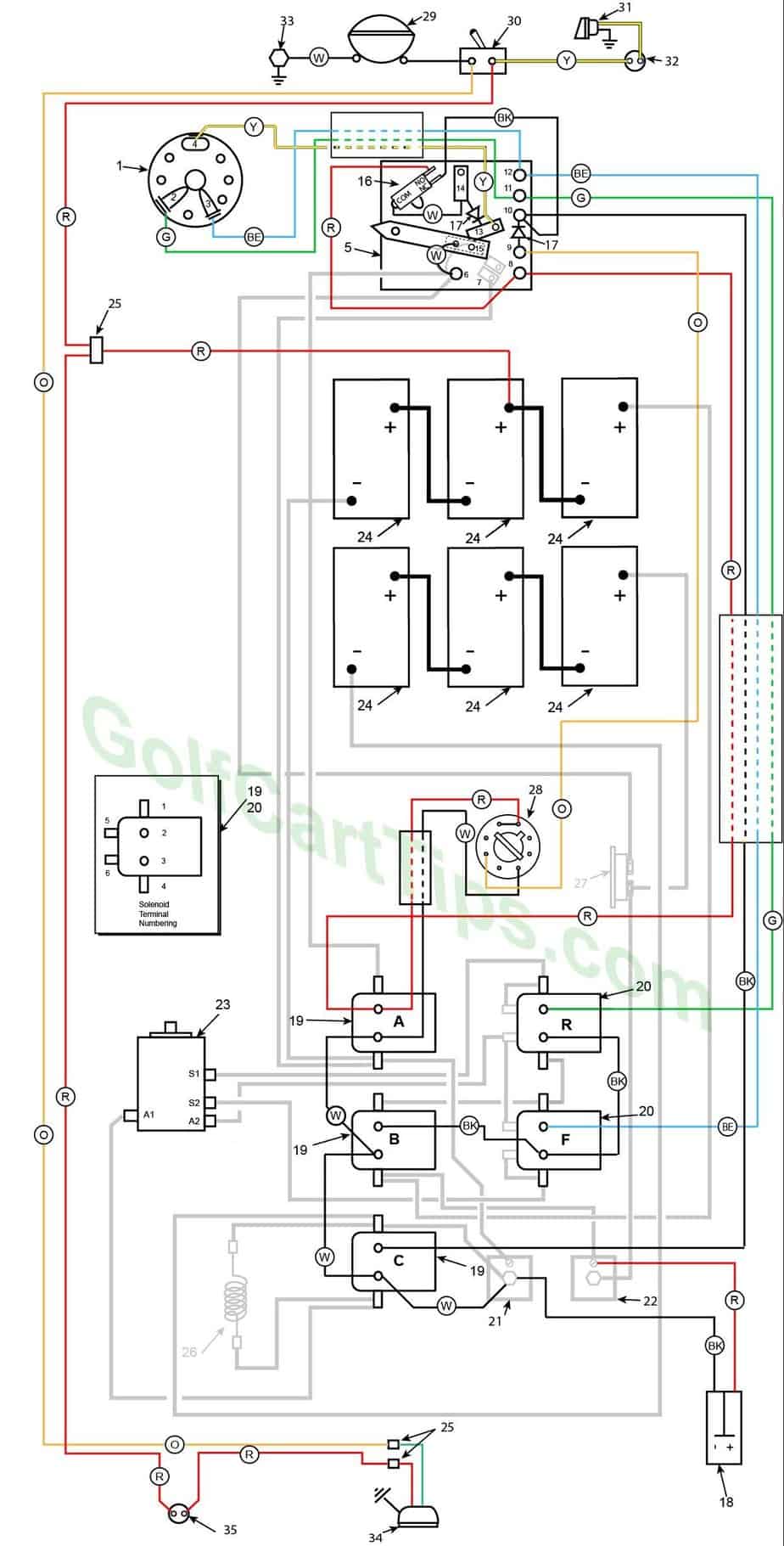
Harley Davidson Golf Cart Wiring Diagrams
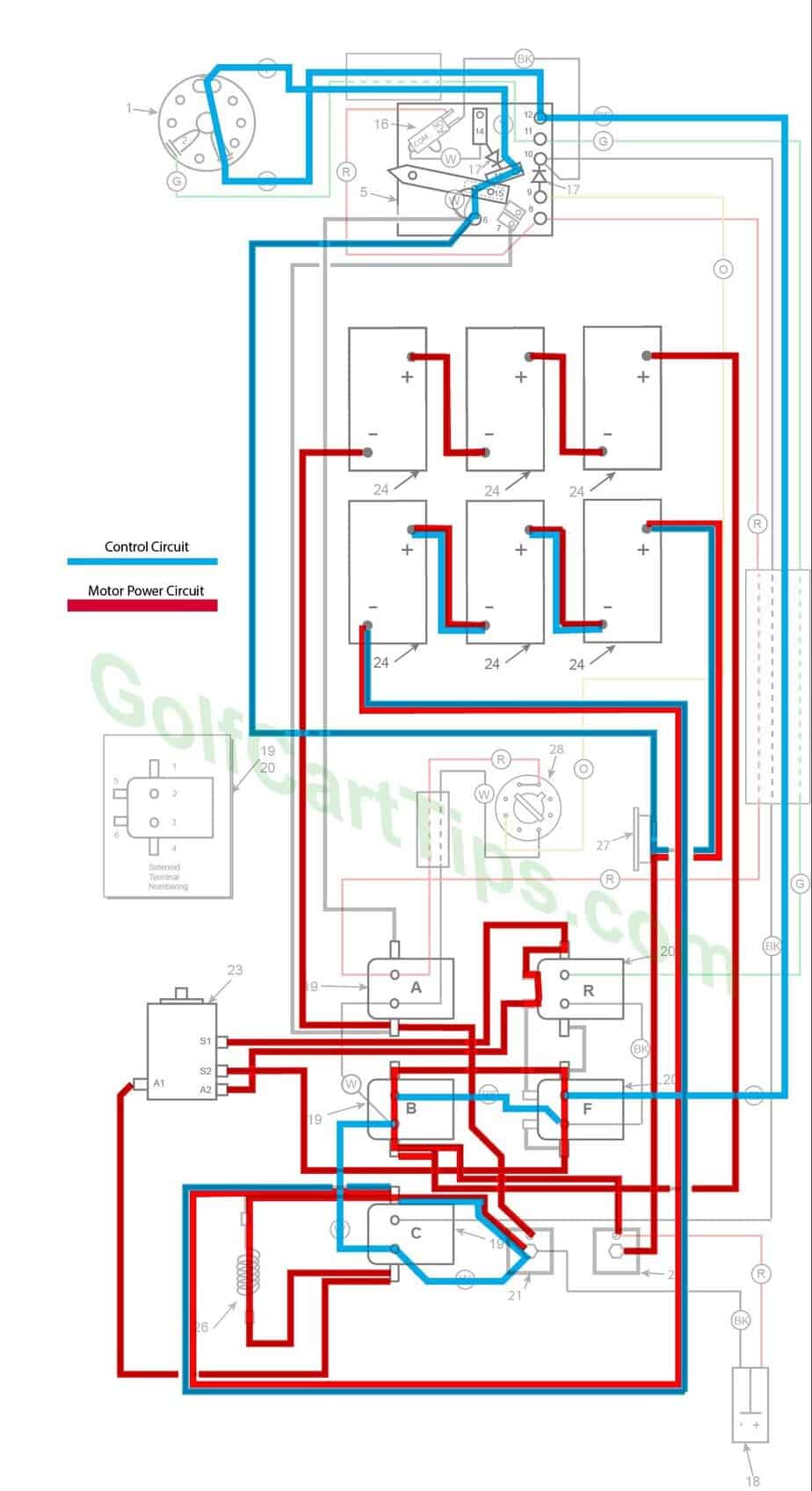
1969-70 Model DEC Control Circuit Wiring Diagram for 16 Gauge Wire
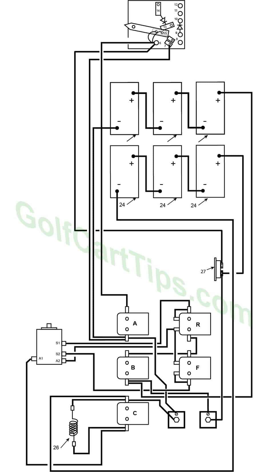
1969-70 Model DEC Heavy Cable Diagram
Charging

- Key switch – Off
- Speed Switch – at resting stop
- Solenoid “A” Open – Voltage not applied to small terminals
- Solenoid “B” Open – Voltage not applied to small terminals
- Solenoid “C” Open – Voltage not applied to small terminals
- Solenoid “F” Open – Voltage not applied to small terminals – Bottom terminals closed
- Solenoid “R” Open – Voltage not applied to small terminals – Bottom terminals closed
- Voltage to Motor – None
- Voltage across A1 and A2 – None
- Motor Diodes – None
- Speed Switch Diode – None
- Time Delay – Open
- Micro Switch – NO Open NC Closed
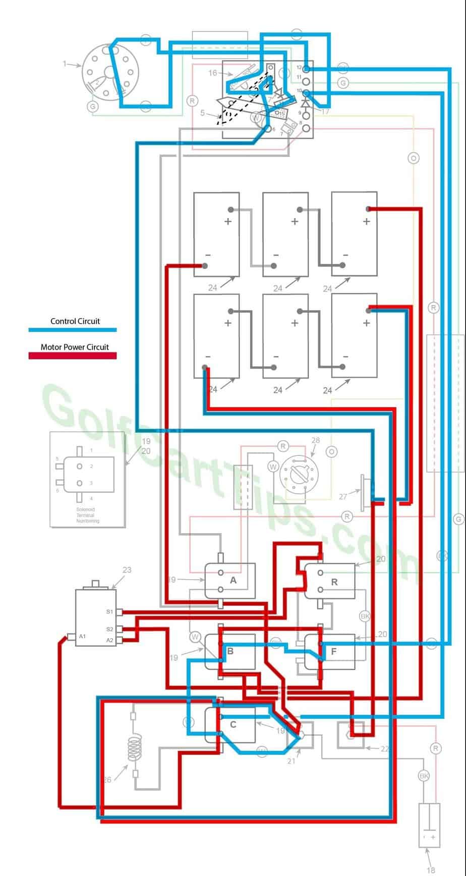
First Speed
- Key switch – Forward
- Speed Switch – Contact #3
- Solenoid “A” Open – Voltage not applied to small terminals
- Solenoid “B” Closed – Voltage applied to small terminals, continuity across large terminals
- Solenoid “C” Open – Voltage not applied to small terminals
- Solenoid “F” Closed – Voltage applied to small terminals, continuity across large terminals – Bottom terminals open
- Solenoid “R” Open – Voltage not applied to small terminals – Bottom terminals closed
- Voltage to Motor – 18-volts through the Resistor
- Voltage across A1 and A2 – 12-volts
- Left Motor Diode – Current flowing from Solenoid “A” to Solenoid “B”
- Right Motor Diode – Current flowing from Solenoid “C” to Solenoid “A”
- Speed Switch Diode – Blocks current from Speed Switch fourth Contact
- Time Delay – Open
- Micro Switch – Open
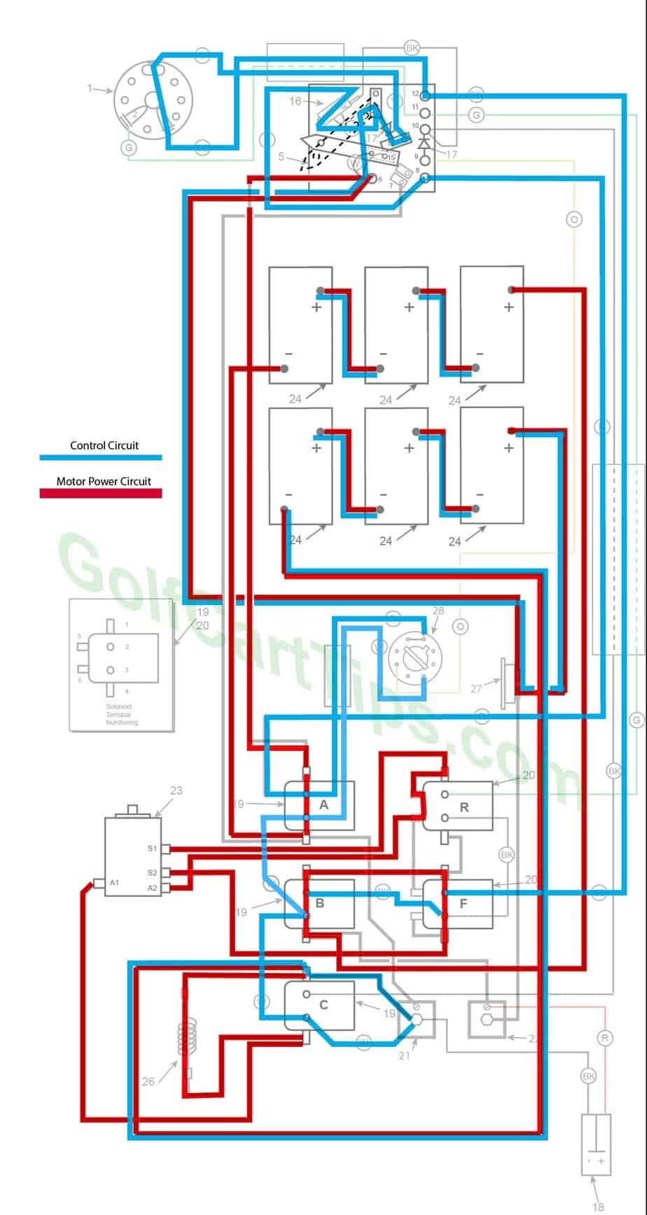
Second Speed
- Key switch – Forward
- Speed Switch – Contact #4 Micro Switch not depressed yet
- Solenoid “A” Open – Voltage not applied to small terminals
- Solenoid “B” Closed – Voltage applied to small terminals, continuity across large terminals
- Solenoid “C” Closed – Voltage applied to small terminals, continuity across large terminals
- Solenoid “F” Closed – Voltage applied to small terminals, continuity across large terminals – Bottom terminals open
- Solenoid “R” Open – Voltage not applied to small terminals – Bottom terminals closed
- Voltage to Motor – 18-volts bypassing the Resistor
- Voltage across A1 and A2 – 15.5-volts to 16.5-volts
- Left Motor Diode – Current flowing from Solenoid “A” to Solenoid “B”
- Right Motor Diode – Current flowing from Solenoid “C” to Solenoid “A”
- Speed Switch Diode – Allows current from Speed Switch to third Speed Switch Contact and on to Solenoid “B” and “F”
- Time Delay – Open
- Micro Switch – not activated but allowing current to pass to power Solenoid “C”
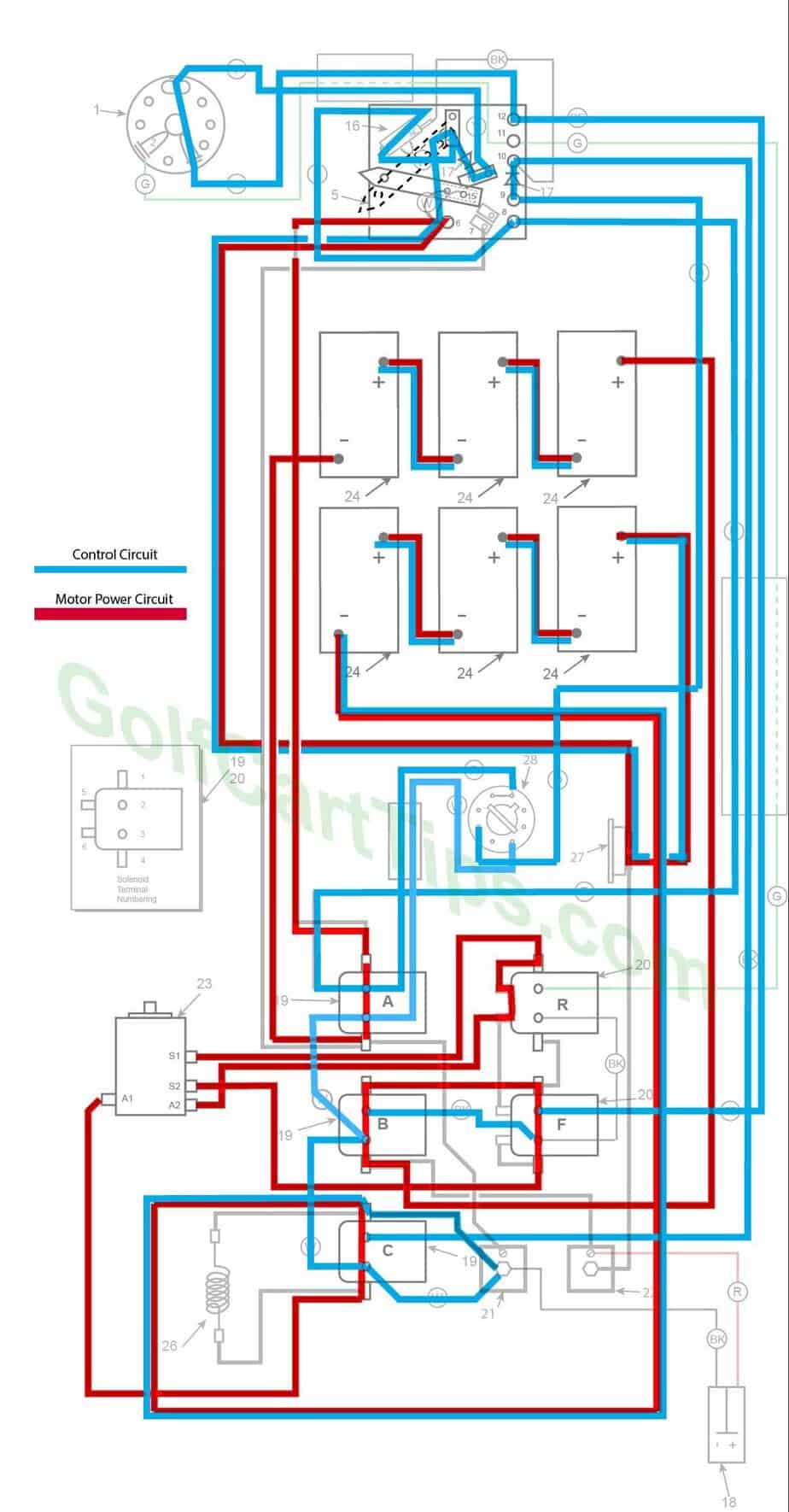
Third Speed
- Key switch – Forward
- Speed Switch – Contact #4 Micro Switch has depressed
- Solenoid “A” Closed – Voltage applied to small terminals, continuity across large terminals
- Solenoid “B” Closed – Voltage applied to small terminals, continuity across large terminals
- Solenoid “C” Open – Voltage not applied to small terminals
- Solenoid “F” Closed – Voltage applied to small terminals, continuity across large terminals – Bottom terminals open
- Solenoid “R” Open – Voltage not applied to small terminals – Bottom terminals closed
- Voltage to Motor – 36-volts through the Resistor
- Voltage across A1 and A2 -30.5-volts to 31.5-volts
- Left Motor Diode – Blocking current flowing from Solenoid “A” to Solenoid “C”
- Right Motor Diode – Blocking current flowing from Solenoid “B” to Solenoid “A”
- Speed Switch Diode – Allows current from Speed Switch to third Speed Switch Contact and on to Solenoid “B” and “F”
- Time Delay – Actuated and powering Solenoid “C” after 1.8 seconds
- Micro Switch – Activated and powering Solenoid “A” and Time Delay
Fourth Speed
- Key switch – Forward
- Speed Switch – Contact #4 Micro Switch has depressed
- Solenoid “A” Closed – Voltage applied to small terminals, continuity across large terminals
- Solenoid “B” Closed – Voltage applied to small terminals, continuity across large terminals
- Solenoid “C” Closed – Voltage applied to small terminals, continuity across large terminals
- Solenoid “F” Closed – Voltage applied to small terminals, continuity across large terminals – Bottom terminals open
- Solenoid “R” Open – Voltage not applied to small terminals – Bottom terminals closed
- Voltage to Motor – 36-volts bypassing the Resistor
- Voltage across A1 and A2 -33.5-volts to 34.5-volts
- Left Motor Diode – Blocking current flowing from Solenoid “A” to Solenoid “C”
- Right Motor Diode – Blocking current flowing from Solenoid “B” to Solenoid “A”
- Speed Switch Diode – Allows current from Speed Switch to third Speed Switch Contact and on to Solenoid “B” and “F”
- Time Delay – Actuated and powering Solenoid “C”
- Micro Switch – Activated and powering Solenoid “A” and Time Delay
Reverse (Fourth Speed Shown)

- Key switch – Reverse
- Speed Switch – Same as Forward Speeds
- Solenoid “A” – Same as Forward Speeds
- Solenoid “B” – Same as Forward Speeds
- Solenoid “C” – Same as Forward Speeds
- Solenoid “F” Open – Voltage not applied to small terminals – Bottom terminals closed
- Solenoid “R” Closed – Voltage applied to small terminals, continuity across large terminals – Bottom terminals open
- Voltage to Motor – Same as Forward Speeds
- Voltage across A1 and A2 -Same as Forward Speeds
- Left Motor Diode – Same as Forward Speeds
- Right Motor Diode – Same as Forward Speeds
- Speed Switch Diode – Same as Forward Speeds
- Time Delay – Same as Forward Speeds
- Micro Switch – Same as Forward Speeds
Solenoid Arrangement
Numbering Key for 1969 – 1970 Diagrams
- Key Switch – 3 wires (Green, Blue, Yellow) For terminals 2, 3, and 4
- Key Switch Terminal – Green wire to Speed Switch Connection 11
- Key Switch Terminal – Blue wire to Speed Switch Connection 12
- Key Switch Terminal – Yellow wire to Speed Selector Switch 13
- Speed Switch (Contains Terminals 6, 7, 8, 9, 10, 11, 12, 13 and 14)
- Speed Switch Terminal – White wire to Terminal 15 on Switch Arm (2), Black wire to Solenoid Terminal A1, Black wire to Circuit Breaker 27 – 4 wires
- Speed Switch Terminal – Black wire to Solenoid Terminal A4
- Speed Switch Terminal – Red wire to Micro Switch NO terminal, Red wire to Solenoid Terminal A2
- Speed Switch Terminal – Orange wire to Time Delay Tube Pin 5, Diode connected to Speed Switch Terminal 10
- Speed Switch Terminal – Diode to Key Switch Terminal 9, Black wire to Solenoid Terminal C2, and Black wire to Micro Switch NC Terminal
- Speed Switch Terminal – Green wire to Key Switch Terminal 2, and Green wire to Solenoid Terminal R2
- Speed Switch Terminal – Blue wire to Solenoid Terminal F2, Blue wire to Key Switch Terminal 3
- Speed Switch Terminal – Yellow wire to Key Switch Terminal 4, Diode to Speed Switch Terminal 14
- Speed Switch Terminal – White wire to Micro Switch Common, Diode to Speed Switch Terminal 13
- Speed Switch Wiper Arm – White wire (2) to Speed Switch Terminal 6
- Micro Switch – White wire to Speed Switch Terminal 14, Red wire to Speed Switch Terminal 8, Black wire to Speed Switch Terminal 10
- Diode (2)
- Charger Connection Plug – Negative Terminal 1 Black wire to Left Motor Diode, Red wire to Right Motor Diode
- Solenoids A, B, and C
Solenoid A
A1 – Black wire to Speed Switch Terminal 6
A2 – Red wire to Time Delay Tube pin #8, Red wire to Speed Switch Terminal 8
A3 – White wire to Time Delay Tube Pin # 2, White wire to Solenoid Terminal B3
A4 – Black wire to Left Motor Diode, Black Wire to Circuit Breaker 27, Black wire to Speed Switch Terminal 7
Solenoid B
B1 – Copper Strap to Solenoid Terminal F1
B2 – Black wire to Solenoid Terminal F3
B3 – White wire to Solenoid Terminal A3, White wire to Solenoid Terminal C3
B4 – Black wire to Right Motor Diode 22, Black wire to Battery Positive Post
Solenoid C
C1 – Black Wire to Battery Negative Post, Black wire to Resistor 26, Black wire to Left Motor Diode 21
C2 – Black wire to Speed Switch Terminal 10
C3 – White wire to Left Motor Diode 21, White wire to Solenoid Terminal B3
C4 – Black wire to Resistor 26, Black wire to Motor Terminal A1 - Solenoids R and F
Solenoid R
R1 – Copper Strap ti Solenoid Terminal R5, Black wire to Motor Terminal S1
R2 – Green wire to Speed Switch Terminal 11
R3 – Black wire to Solenoid Terminal F3
R4 – Copper Strap to Solenoid Terminal F1
R5 – Copper Strap to Solenoid Terminal R1
R6 – Copper Strap to Solenoid Terminal F5, Black wire to Motor Termina A2
Solenoid F
F1 – Copper Strap to Solenoid Terminal R4, Black wire to Solenoid Terminal B2
F2 – Blue wire to Speed Switch Terminal 12
F3 – Black wire to Solenoid Terminal R3, Black wire to Solenoid Terminal B2
F4 – Copper Strap to Solenoid Terminal F6, Black wire to Motor Terminal S2
F5 – Copper Strap to Solenoid Terminal R6
F6 – Copper Strap to Solenoid Terminal F4 - Left Motor Diode
- Right Motor Diode
- Motor – 4 wires
A1 – Black wire to Solenoid Terminal C4
A2 – Black wire to Solenoid Terminal R6
S1 – Black Wire to Solenoid Terminal R1
S2 – Black Wire to Solenoid Terminal F4 - Batteries – Six 6-volt in series 36-volt, and two sets of 3 in series 18-volt
- Connector
- Resistor – Black wire to Solenoid Terminal C1, Black wire to Solenoid Terminal C4
- Circuit Breaker
- Delay Tube – Pin 2 White wire to Solenoid Terminal A3, Pin 5 Orange wire to Speed Switch Terminal 9, Pin 8 Red wire to Solenoid Terminal A2
- Headlight
- Headlight Switch
- Horn
- Horn Button
- Ground Bolt – White wire to Headlight
- Tail Light – Green wire to Connector 25, Red wire to Connector 25
- Brake Stop Switch – Red wire to Connector 25, Red wire to Connector 25 (2)
Troubleshooting Chart for the 1969-1970 Model DEC
| Symptom | Possible Cause | Remedy |
|---|---|---|
| Batteries will not charge | Accelerator pedal not at rest position and wiper arm is not completely on the first contact block | Refer to Speed Switch Adjustment Section here |
| Corroded or loose battery connections | Check, clean and tighten connections | |
| Faulty Battery | Test each Battery while completely disconnected from the series | |
| Faulty Charger | Use multimeter and test output voltage | |
| Will not go in forward or reverse | Faulty batteries or connections | Inspect batteries and clean connections |
| Faulty key switch | Test key switch with continuity tester | |
| Faulty speed switch | Check speed switch connections | |
| Solenoid "B" not energizing | Check cabling to Solenoid "B" Test solenoid with procedure listed here |
|
| Faulty Motor | Follow Motor trouble shooting procedures | |
| Forward Works, no reverse | Faulty key switch | Test key switch with continuity tester |
| Solenoid "R" not energizing | Check cabling to Solenoid "R" Test solenoid with procedure listed here |
|
| Solenoid "F" open between Large bottom terminals | Check connections to Solenoid "B" large terminals. Test solenoid with procedure listed here |
|
| Reverse works OK, no Forward | Faulty key switch | Test key switch with continuity tester |
| Solenoid "R" open circuit on large bottom terminals | Check connections to Solenoid "R" large terminals. Test solenoid with procedure listed here |
|
| Solenoid "F" not Energizing | Check connections to Solenoid "F" control terminals. Test solenoid with procedure listed here |
|
| Speed 1 Works, no 2, 3, or 4 | Speed Switch wiper arm not making contact with 4th speed contact pad. | Remove and inspect Speed Switch. |
| Speed Switch diode open | Check diode leads. | |
| Speed 1 and 2 Works, no 3, or 4 | Micro switch not making the connection between NC and COM | Test Micro Switch |
| Solenoid "A" not energizing, stuck open | Check connections to Solenoid "A" terminals. Test solenoid with procedure listed here |
|
| Speed 3 and 4 Works, no 1 or 2 | Both Motor diodes open | Check diode condition |
| Solenoid "A" stuck closed | Check connections to Solenoid "A" control terminals. Test solenoid with procedure listed here |
|
| Speed 3 and 4 works, no 1, or 2 | Short in Speed Switch Diode | Inspect, repair, or replace. |
| Speed 2 and 4 works, no 1 or 3 | Solenoid "C" stuck closed bypassing Resistor | Test solenoid "C" with procedure listed here |
| Open Resistor | Check Resistor connections. | |
| Speed 1 and 3 works, no 2 or 4 | Solenoid "C" not energizing or stuck open passing all current through Resistor | Test solenoid "C" with procedure listed here |
| Speed 1 and 4 works, no 2 or 3 | Time Delay Tube shorted | Check Time Delay Tube connections. |
| Speed 1, 2, and 3 works, no 4 | Time Delay Tube open or faulty | Check Time Delay Tube connections. |
| Speed 3 has a long delay or too short of a delay | Time Delay Tube open faulty | Test Time Delay Tube. |
| Front set of batteries goes dead or Rear set of batteries goes dead | One Motor Diode is open | Check connections to Motor Diode or replace. |
Conclusion
The battery configuration changed with the 1969 DEC putting the 6 batteries in the front and turned lengthwise. After 1970 the models DE, DE-3 and DE-4 continue with the Three and Four Wheel model carts.
Other Years and Models for The Harley Davidson Golf Cart
- Harley Davidson 1963-82 Model D, DC, and DF
- Harley Davidson Model DE 1963 To 1966
- Harley Davidson Model DE 1967-1978
- Harley Davidson 1979–1982 DE, DE4
- Harley Davidson Model DEC 1966 to 1968