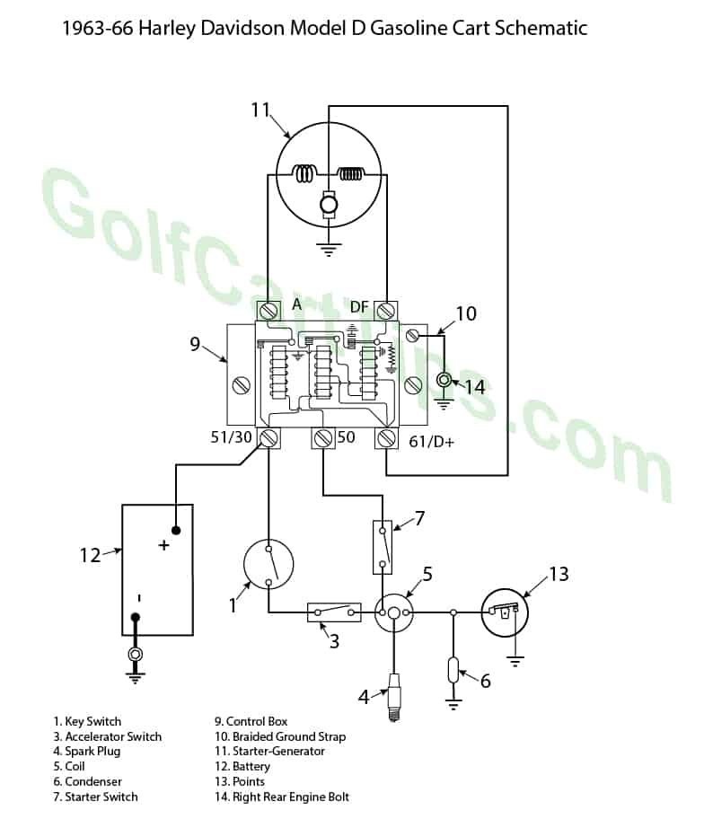
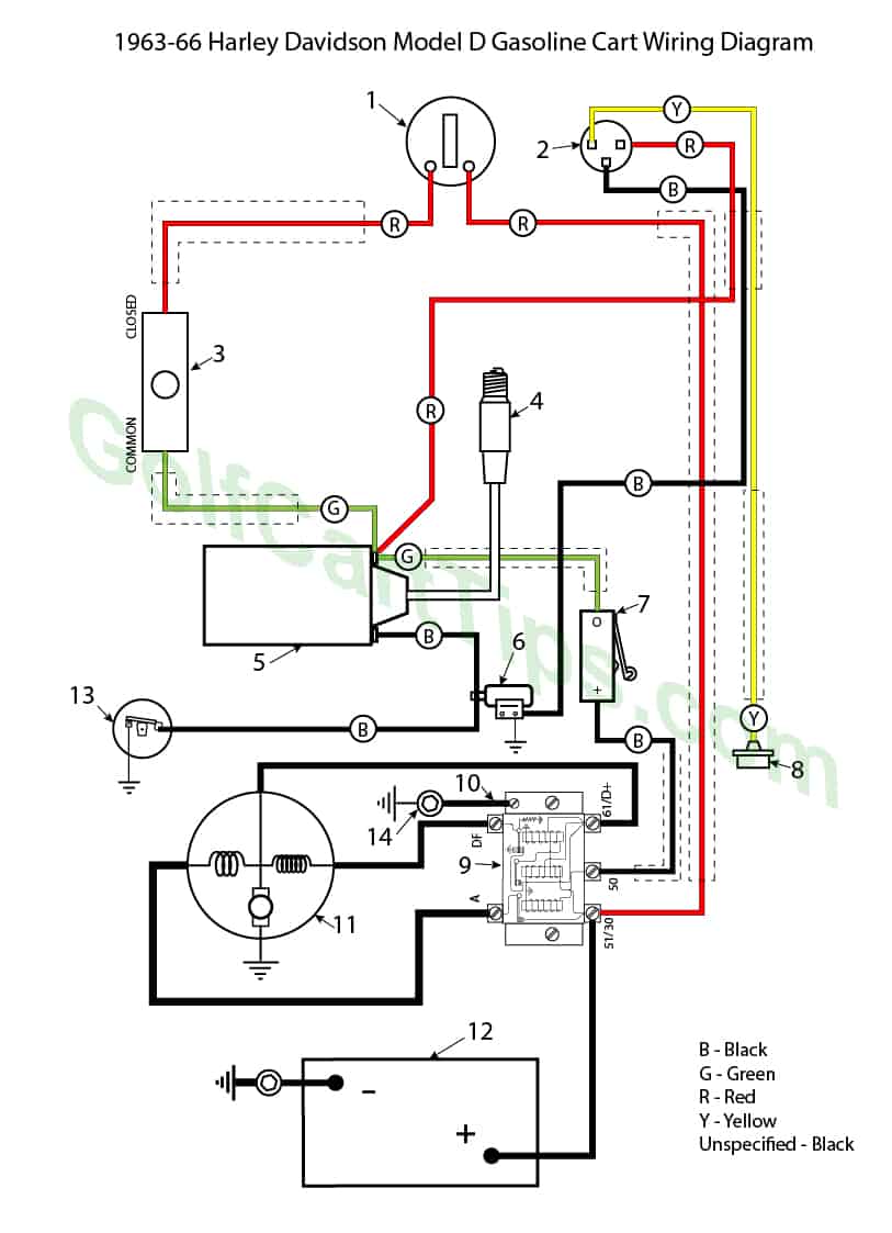
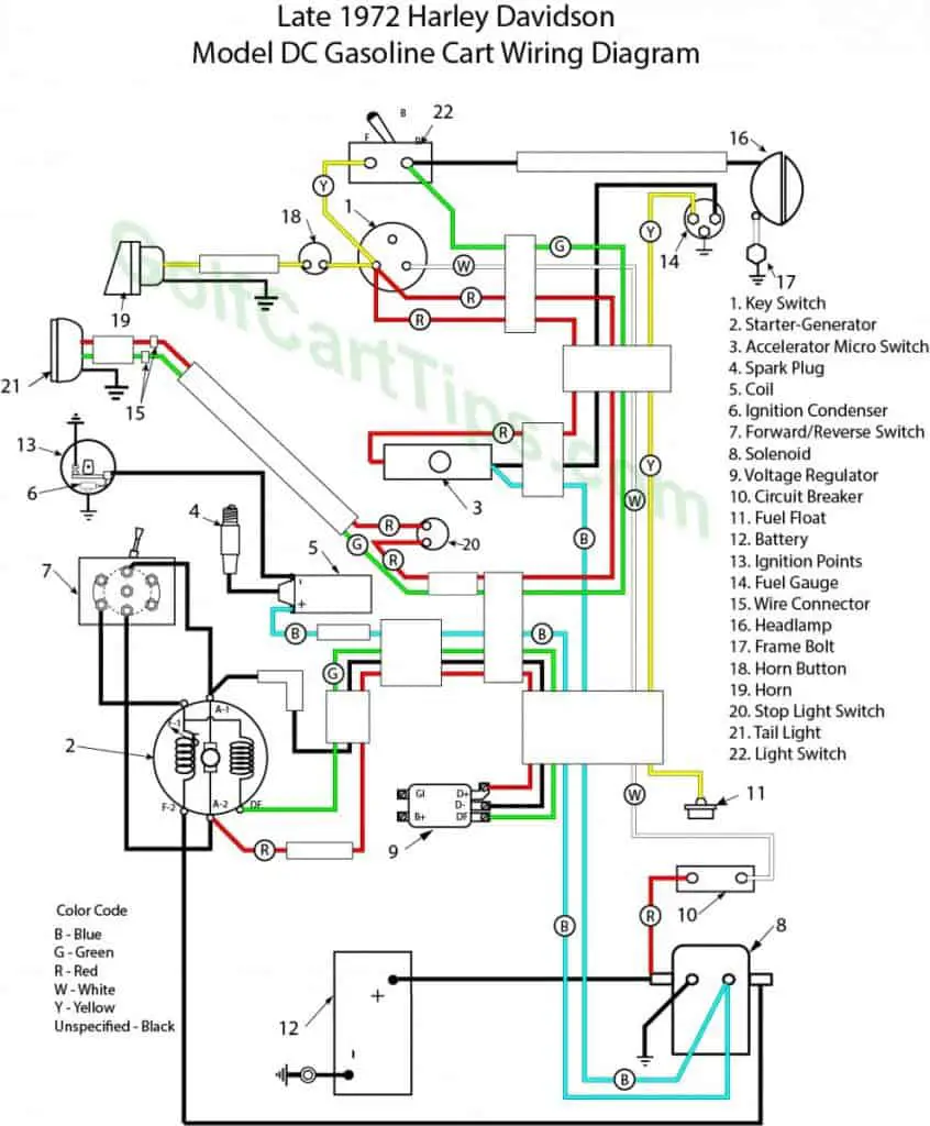
Wiring for 1963-66 Model D and 1963-68 Model DC
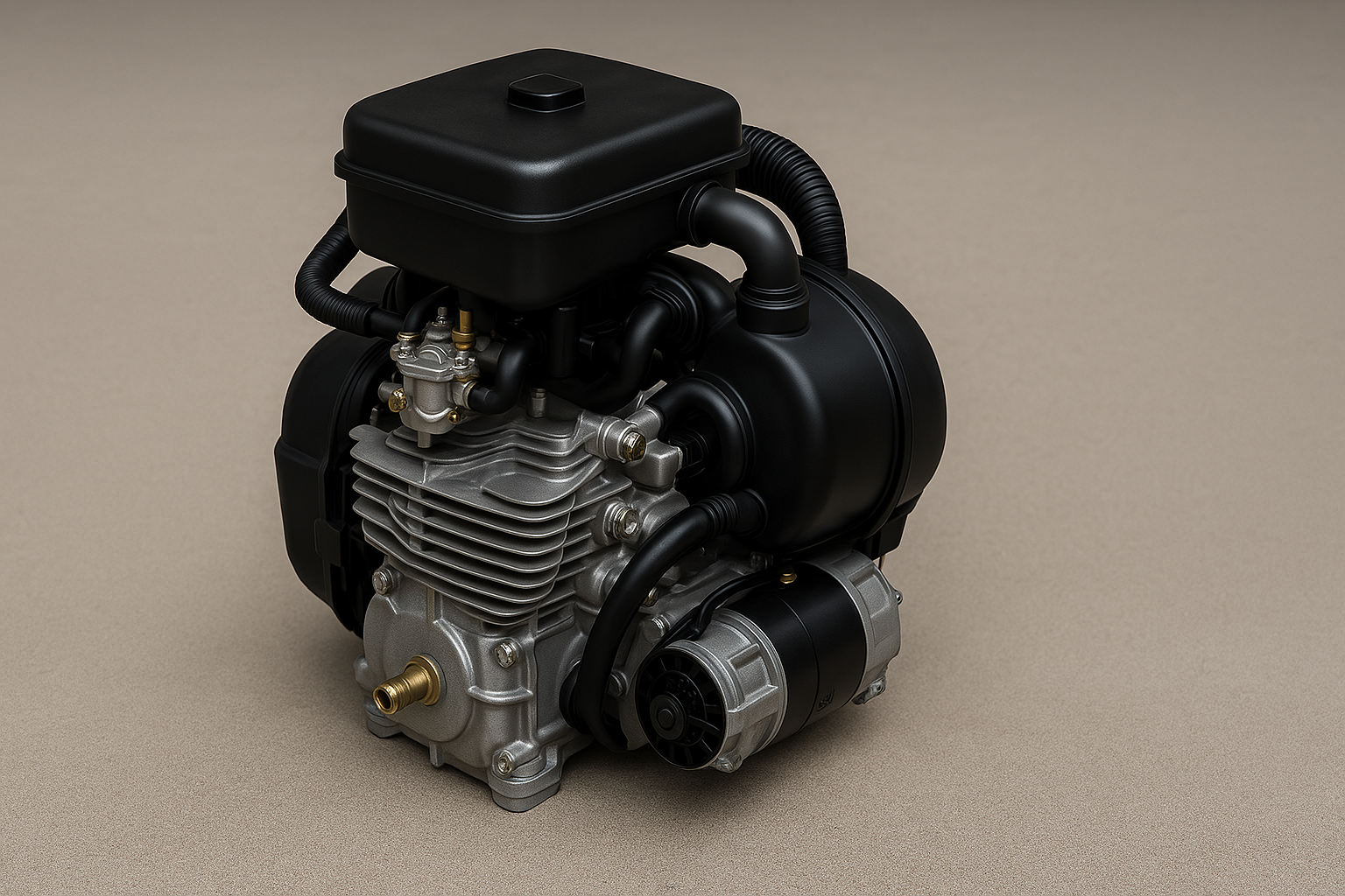
The Harley Davidson gasoline cart has a 12-volt electrical system utilizing a combination starter motor/generator unit built into the engine crankcase, in conjunction with a control switch-box-regulator unit and a storage battery using a negative grounded system.
Ignition spark is produced by a 12-volt coil through a cam operated circuit breaker with built-in automatic advance mechanism.
Main components of the starter-generator unit are the field stator with 12 radial field coils, and the bell-shaped armature rotor with the commutator formed on its inner vertical face; The armature is mounted directly on the engine crankshaft end taper (right side) and rotates at engine speed.
Six alternate field pole shoes of the stator are series-wound with heavy gauge wire for starting; the other six carry lighter gauge shunt field windings for generating power. Mounted on the stator housing are four spring-loaded carbon brushes which contact the armature commutator.
Components of the control system are the switch box assembly (containing voltage regulator, cutout relay and starter solenoid), two micro-switches (3,7) and a keyswitch (1).
Starter
When starting the engine, the 6 stator field coils are connected in series with the armature to operate as a series motor. This circuit is controlled by the key switch (1) and two micro-switches (3 and 7), which operate a solenoid starter switch in the control box (9), which controls the main starter current. These three control switches (1, 3 and 7) are series connected with the battery and solenoid coil of the main starter switch. With key switch (1) turned to “ON”, battery current is available at the microswitch (3), which is open until the accelerator pedal is pushed. When the pedal is depressed contact button on microswitch (3), is released, contacts close, turning on ignition circuit. Battery current also flows through micro-switch (7) to terminal No. 50 on the control box, energizing the solenoid coil of the starter switch closing switch contacts. Battery current flows to the starter motor. Starter motor now functions to crank the engine.
Micro-switch (7) is mounted in a position so that the operating finger roller touches the transmission drive cup cover. This switch is normally closed, however, as the engine starts and operates at driving speed, the drive cup cover moves away from the switch allowing its contacts to open. This interrupts the current flow through the starter relay winding causing the relay switch contacts to open, stopping current flow to the starter motor which ceases to operate.
The engine can be stopped by turning the key switch to “OFF” position or by allowing accelerator pedal to come to its full outward position, opening microswitch (3), which opens the ignition circuit. When the engine stops, the outward movement of the transmission drive cup cover pushes on the finger of micro-switch (7) closing the switch contacts. When the contacts of either switch (1 or 3) are open, the current flow to the ignition coil (5) is interrupted to stop the engine.
Generator
When the generator is driven by the engine, the stator shunt field coils are excited and the current generated in the armature is utilized for the ignition system and charging the battery. The generator output is limited by the voltage regulator, which controls the generator field strength.
The generated voltage increases with engine speed and as soon as the rated level (approximately 12 volts) has been reached, the cutout switch closes and charging of the battery begins. When running, this voltage is maintained nearly constant by the voltage regulator, regardless of engine speed.
As current is consumed, the voltage drops in conformity with the output. The prescribed charging rate is reached at speeds varying between 1200 and 1500 RPM and will meet a continuous load of 90 watts thereafter.
As the engine speed is reduced and generated voltage drops below rated level, the cutout relay contacts will open, disconnecting the generator from the battery circuit to prevent discharging of the battery through the armature circuit.
Reverse On 1963-66
A reversing unit provides forward and reverse motion as well as gear reduction for the 63-66 carts. The unit consists of an upper and lower case which house the forward gear, reverse gear, and shifter clutch assemblies mounted on a drive shaft and a driven gear assembly which is connected externally by coupling to the differential and axles.
The unit is controlled by a shift lever which locates the forward, reverse and neutral positions of the shifter clutches.
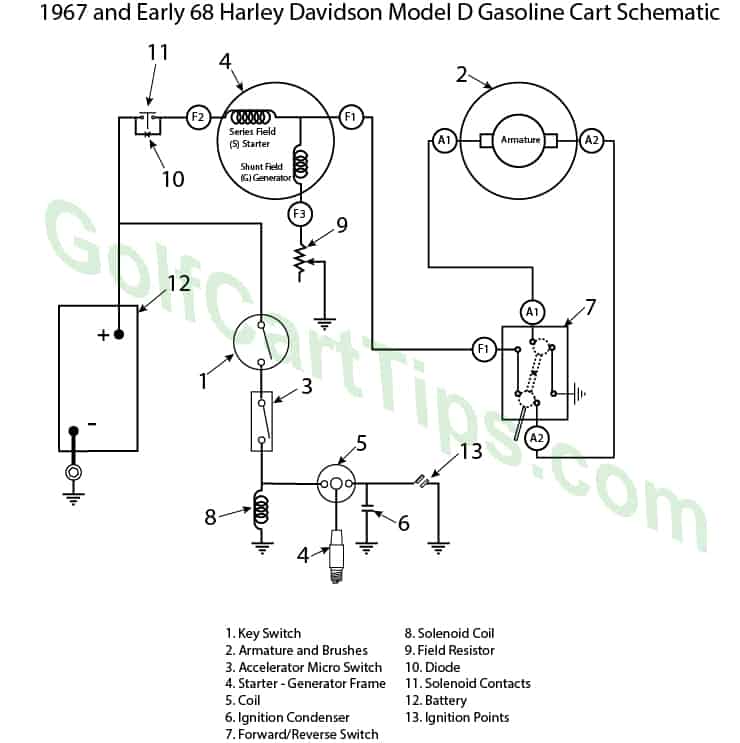
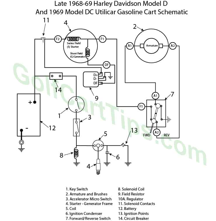
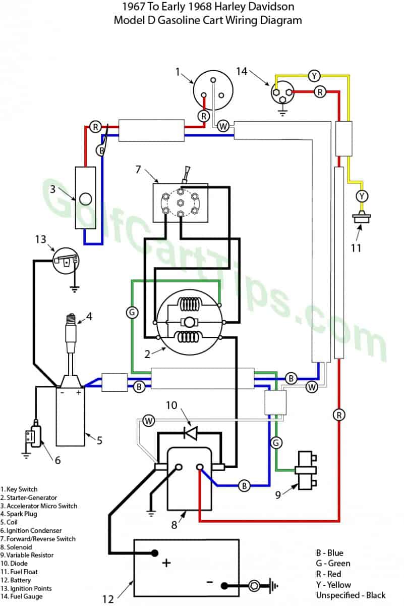
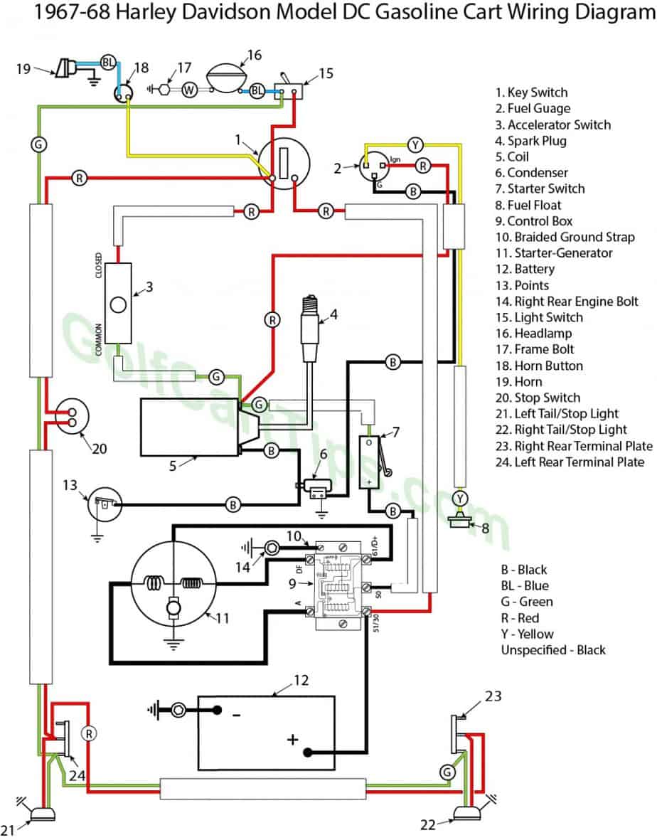
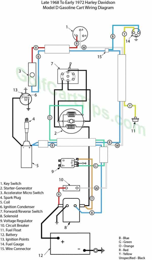
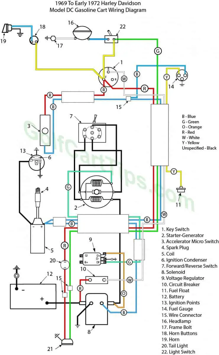
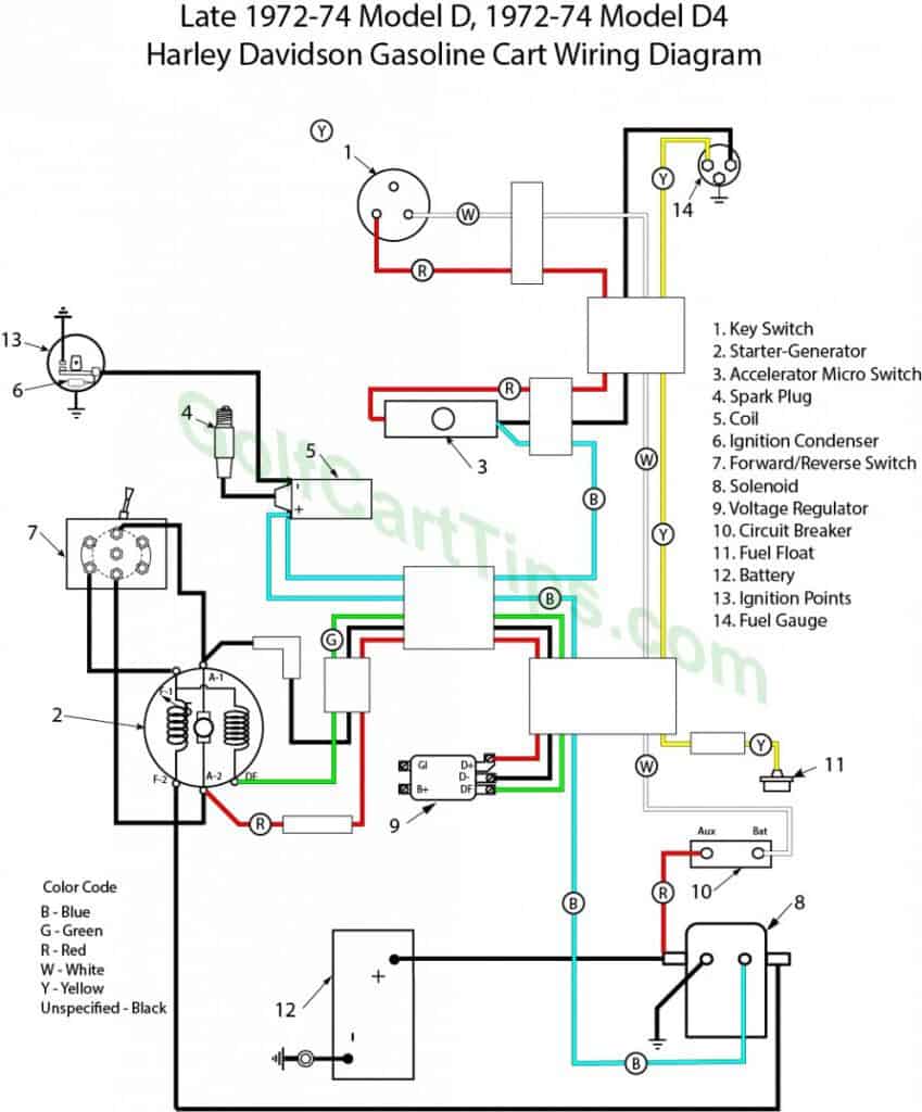
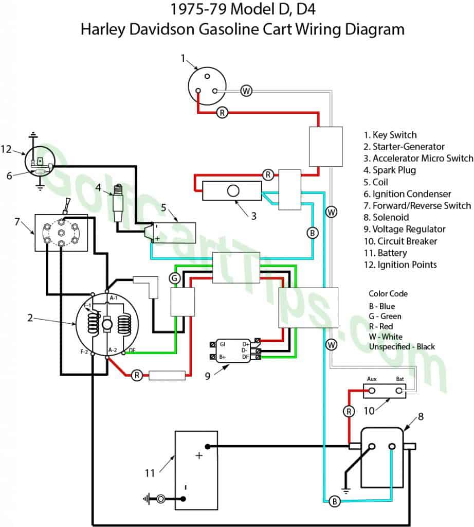
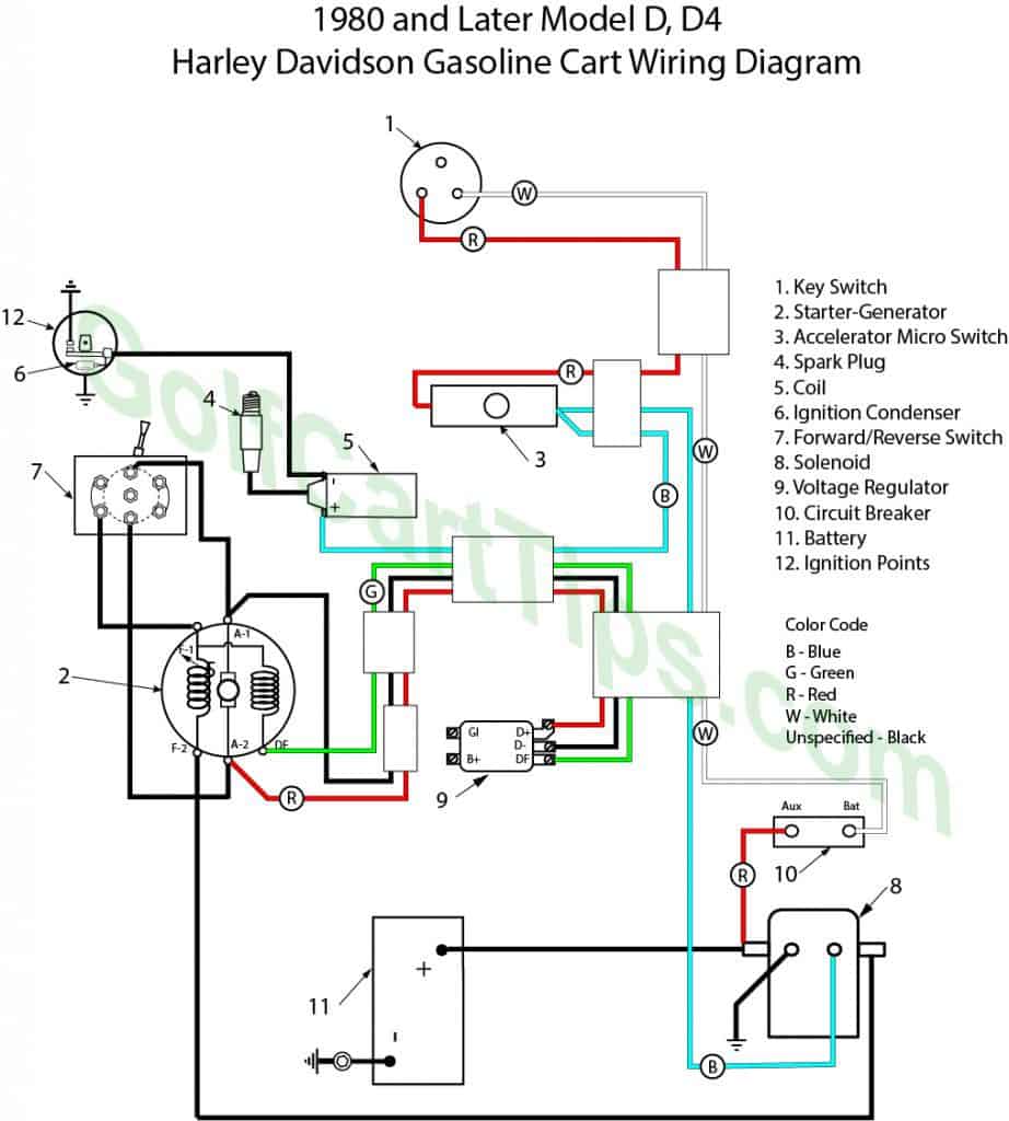
1967 and Later Models
The Gasoline Cart has a 12-volt electrical system utilizing a belt drive reversible starter motor-generator unit in conjunction with a fixed field resistor or regulator, starter solenoid, and a storage battery using a negative grounded system.
Ignition spark is produced by a 12-volt coil through a cam-operated circuit breaker designed to give correct ignition timing in both forward and reverse engine running directions.
The starter-generator is a separate unit, mounted on the engine and coupled to the engine crankshaft with a V-belt. The starter-generator-to-engine drive ratio is 2 to 1 (2.36 to 1 in 1980).
There are two sets of windings in the frame (4). One set (S) is wound with heavy gauge wire for starting and the other set (G) carries lighter gauge wire for generating. Armature (2) rotation is reversed by means of an external switch (7) which reverses the armature current in relation to the field current.
Brushes are mounted on the drive end cover which contacts the armature commutator. Components of the control system are the reversing switch, solenoid switch, adjustable field resistor or regulator, micro-switch and a key switch.
Forward
When starting the engine, the heavy field coils (S) are connected in series with the armature to operate as a series motor. This circuit is controlled by the reversing switch (7) and micro-switch (3) which operates a solenoid starter switch (8), controlling the main starter current.
With key switch (1) turned to “ON”, battery current is available at micro-switch (3), which is open until the accelerator pedal is pushed. When the pedal is depressed contact button on micro switch is released, contacts close, turning on ignition circuit and energizing the solenoid coil of the starter switch closing switch contacts. Battery current flows to the starter motor. Starter motor now functions to crank the engine in the direction determined by the position of reversing switch (7).
Reverse (1967 And Later)
Starting coil (S) and armature coil ends (Al and A2) (brushes) are connected to the reversing switch (7) which changes the direction of armature current in relation to starting field current through switch contacts to ground. This changes the direction of the magnetic field and armature rotation. The starting coils are always connected through the solenoid switch when the cart is operating but will have no effect when the voltage generated by the field winding is above the battery voltage. At this time the direction of current flow instead of coming from the battery goes to the battery.
The engine can be stopped by turning the key switch to “OFF” position or by allowing accelerator pedal to come to its full outward position, opening microswitch (3), which opens ignition circuit to stop the engine.
Generator Function
When engine speed exceeds starter generator speed, the shunt field coils (G) are excited and the current generated in the armature is utilized for the ignition system and charging the battery. The generator output is limited by the adjustable resistor or regulator (9), which controls the strength of the magnetic field produced by the shunt field coils (G). The generator voltage increases with engine speed and as soon as the rated level (approximate ly 15 volts) has been reached, charges the battery and increases with engine speed to its maximum value controlled by the voltage regulator. The prescribed charging rate at governed speed is set by means of a variable resistor or is controlled by the voltage regulator.
On models equipped with field resistor, a diode acts to bleed off the voltage generated by the operation of the cart when coasting with solenoid contacts open (i.e.accelerator pedal released).
Forward/Reverse Switch
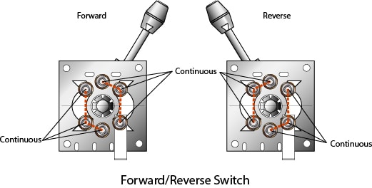
The reversing switch is a built-up assembly which can be taken apart for cleaning and replacement of contact screws, connecting strips, floating contact buttons, etc., if defective. Normally cleaning with fine emery paper is all that is required to correct imperfect contact.
Apply a light coat of high-quality chassis grease to contacts when reassembling switch. Check for continuity with handle in the forward position as shown. For reverse position, check continuity at indicated points.
Other Years and Models for The Harley Davidson Golf Cart