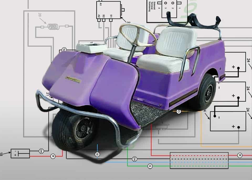
Troubleshooting Harley Davidson golf cart wiring? The following charts and tables will save you hours of online searching and help to pinpoint solutions to the problems this 50-year-old cart may present.
The final two years of the DEC model changed the headlight and taillight options, plus a few 16 gauge wire configuration changes.
Tools needed for troubleshooting include:
- A multimeter or voltmeter
- A 1/2” size wrench
- Electrical tape
- Safety glasses
Harley Davidson Golf Cart Wiring Diagrams
1969-70 Model DEC Control Circuit Wiring Diagram for 16 Gauge Wire
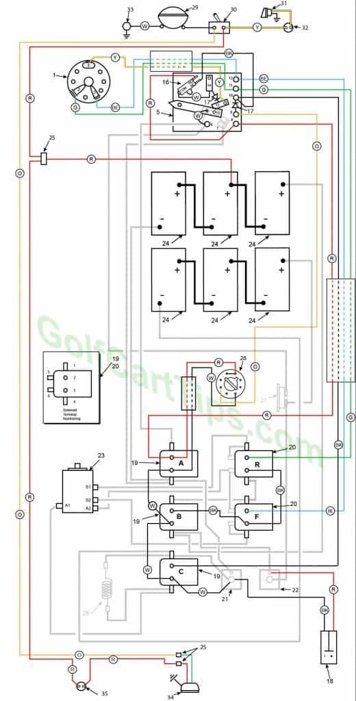
1969-70 Model DEC Heavy Cable Diagram
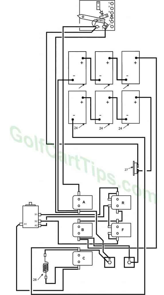
Charging
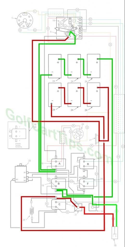
- Key switch – Off
- Speed Switch – at resting stop
- Solenoid “A” Open – Voltage not applied to small terminals
- Solenoid “B” Open – Voltage not applied to small terminals
- Solenoid “C” Open – Voltage not applied to small terminals
- Solenoid “F” Open – Voltage not applied to small terminals – Bottom terminals closed
- Solenoid “R” Open – Voltage not applied to small terminals – Bottom terminals closed
- Voltage to Motor – None
- Voltage across A1 and A2 – None
- Motor Diodes – None
- Speed Switch Diode – None
- Time Delay – Open
- Micro Switch – NO Open NC Closed
First Speed
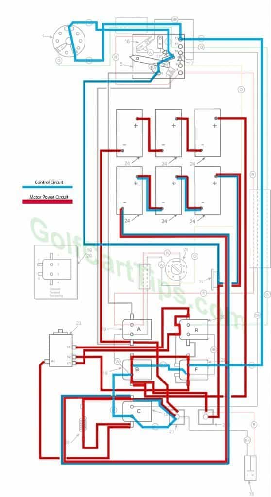
- Key switch – Forward
- Speed Switch – Contact #3
- Solenoid “A” Open – Voltage not applied to small terminals
- Solenoid “B” Closed – Voltage applied to small terminals, continuity across large terminals
- Solenoid “C” Open – Voltage not applied to small terminals
- Solenoid “F” Closed – Voltage applied to small terminals, continuity across large terminals – Bottom terminals open
- Solenoid “R” Open – Voltage not applied to small terminals – Bottom terminals closed
- Voltage to Motor – 18-volts through the Resistor
- Voltage across A1 and A2 – 12-volts
- Left Motor Diode – Current flowing from Solenoid “A” to Solenoid “B”
- Right Motor Diode – Current flowing from Solenoid “C” to Solenoid “A”
- Speed Switch Diode – Blocks current from Speed Switch fourth Contact
- Time Delay – Open
- Micro Switch – Open
Second Speed
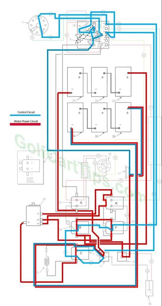
- Key switch – Forward
- Speed Switch – Contact #4 Micro Switch not depressed yet
- Solenoid “A” Open – Voltage not applied to small terminals
- Solenoid “B” Closed – Voltage applied to small terminals, continuity across large terminals
- Solenoid “C” Closed – Voltage applied to small terminals, continuity across large terminals
- Solenoid “F” Closed – Voltage applied to small terminals, continuity across large terminals – Bottom terminals open
- Solenoid “R” Open – Voltage not applied to small terminals – Bottom terminals closed
- Voltage to Motor – 18-volts bypassing the Resistor
- Voltage across A1 and A2 – 15.5-volts to 16.5-volts
- Left Motor Diode – Current flowing from Solenoid “A” to Solenoid “B”
- Right Motor Diode – Current flowing from Solenoid “C” to Solenoid “A”
- Speed Switch Diode – Allows current from Speed Switch to third Speed Switch Contact and on to Solenoid “B” and “F”
- Time Delay – Open
- Micro Switch – not activated but allowing current to pass to power Solenoid “C”
Third Speed
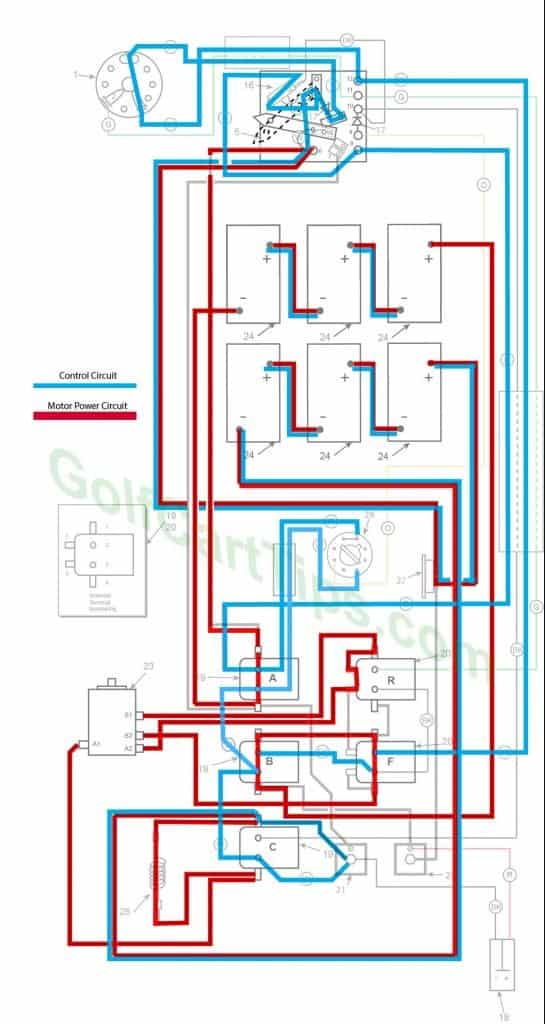
- Key switch – Forward
- Speed Switch – Contact #4 Micro Switch has depressed
- Solenoid “A” Closed – Voltage applied to small terminals, continuity across large terminals
- Solenoid “B” Closed – Voltage applied to small terminals, continuity across large terminals
- Solenoid “C” Open – Voltage not applied to small terminals
- Solenoid “F” Closed – Voltage applied to small terminals, continuity across large terminals – Bottom terminals open
- Solenoid “R” Open – Voltage not applied to small terminals – Bottom terminals closed
- Voltage to Motor – 36-volts through the Resistor
- Voltage across A1 and A2 -30.5-volts to 31.5-volts
- Left Motor Diode – Blocking current flowing from Solenoid “A” to Solenoid “C”
- Right Motor Diode – Blocking current flowing from Solenoid “B” to Solenoid “A”
- Speed Switch Diode – Allows current from Speed Switch to third Speed Switch Contact and on to Solenoid “B” and “F”
- Time Delay – Actuated and powering Solenoid “C” after 1.8 seconds
- Micro Switch – Activated and powering Solenoid “A” and Time Delay
Fourth Speed
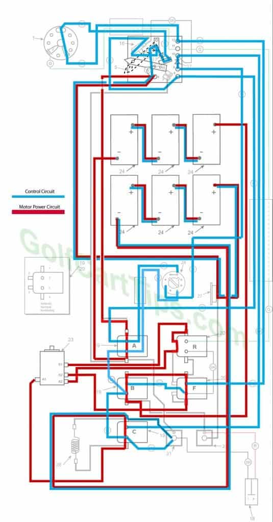
- Key switch – Forward
- Speed Switch – Contact #4 Micro Switch has depressed
- Solenoid “A” Closed – Voltage applied to small terminals, continuity across large terminals
- Solenoid “B” Closed – Voltage applied to small terminals, continuity across large terminals
- Solenoid “C” Closed – Voltage applied to small terminals, continuity across large terminals
- Solenoid “F” Closed – Voltage applied to small terminals, continuity across large terminals – Bottom terminals open
- Solenoid “R” Open – Voltage not applied to small terminals – Bottom terminals closed
- Voltage to Motor – 36-volts bypassing the Resistor
- Voltage across A1 and A2 -33.5-volts to 34.5-volts
- Left Motor Diode – Blocking current flowing from Solenoid “A” to Solenoid “C”
- Right Motor Diode – Blocking current flowing from Solenoid “B” to Solenoid “A”
- Speed Switch Diode – Allows current from Speed Switch to third Speed Switch Contact and on to Solenoid “B” and “F”
- Time Delay – Actuated and powering Solenoid “C”
- Micro Switch – Activated and powering Solenoid “A” and Time Delay
Reverse (Fourth Speed Shown)
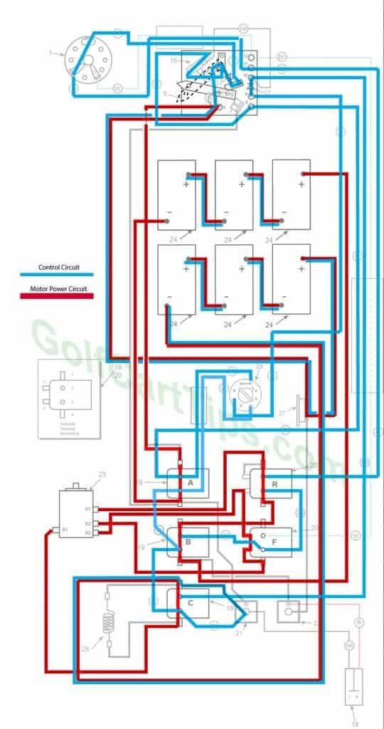
- Key switch – Reverse
- Speed Switch – Same as Forward Speeds
- Solenoid “A” – Same as Forward Speeds
- Solenoid “B” – Same as Forward Speeds
- Solenoid “C” – Same as Forward Speeds
- Solenoid “F” Open – Voltage not applied to small terminals – Bottom terminals closed
- Solenoid “R” Closed – Voltage applied to small terminals, continuity across large terminals – Bottom terminals open
- Voltage to Motor – Same as Forward Speeds
- Voltage across A1 and A2 -Same as Forward Speeds
- Left Motor Diode – Same as Forward Speeds
- Right Motor Diode – Same as Forward Speeds
- Speed Switch Diode – Same as Forward Speeds
- Time Delay – Same as Forward Speeds
- Micro Switch – Same as Forward Speeds
Solenoid Arrangement
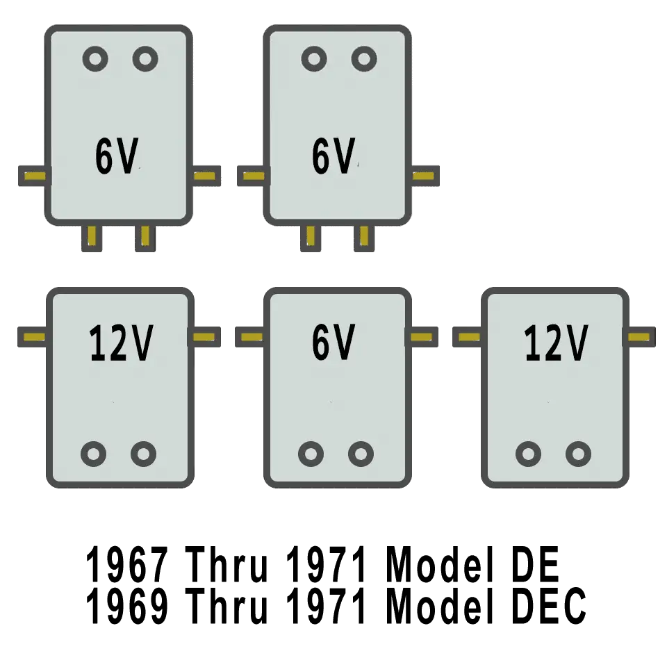
Numbering Key for 1969 – 1970 Diagrams
- Key Switch – 3 wires (Green, Blue, Yellow) For terminals 2, 3, and 4
- Key Switch Terminal – Green wire to Speed Switch Connection 11
- Key Switch Terminal – Blue wire to Speed Switch Connection 12
- Key Switch Terminal – Yellow wire to Speed Selector Switch 13
- Speed Switch (Contains Terminals 6, 7, 8, 9, 10, 11, 12, 13 and 14)
- Speed Switch Terminal – White wire to Terminal 15 on Switch Arm (2), Black wire to Solenoid Terminal A1, Black wire to Circuit Breaker 27 – 4 wires
- Speed Switch Terminal – Black wire to Solenoid Terminal A4
- Speed Switch Terminal – Red wire to Micro Switch NO terminal, Red wire to Solenoid Terminal A2
- Speed Switch Terminal – Orange wire to Time Delay Tube Pin 5, Diode connected to Speed Switch Terminal 10
- Speed Switch Terminal – Diode to Key Switch Terminal 9, Black wire to Solenoid Terminal C2, and Black wire to Micro Switch NC Terminal
- Speed Switch Terminal – Green wire to Key Switch Terminal 2, and Green wire to Solenoid Terminal R2
- Speed Switch Terminal – Blue wire to Solenoid Terminal F2, Blue wire to Key Switch Terminal 3
- Speed Switch Terminal – Yellow wire to Key Switch Terminal 4, Diode to Speed Switch Terminal 14
- Speed Switch Terminal – White wire to Micro Switch Common, Diode to Speed Switch Terminal 13
- Speed Switch Wiper Arm – White wire (2) to Speed Switch Terminal 6
- Micro Switch – White wire to Speed Switch Terminal 14, Red wire to Speed Switch Terminal 8, Black wire to Speed Switch Terminal 10
- Diode (2)
- Charger Connection Plug – Negative Terminal 1 Black wire to Left Motor Diode, Red wire to Right Motor Diode
- Solenoids A, B, and C
Solenoid A
A1 – Black wire to Speed Switch Terminal 6
A2 – Red wire to Time Delay Tube pin #8, Red wire to Speed Switch Terminal 8
A3 – White wire to Time Delay Tube Pin # 2, White wire to Solenoid Terminal B3
A4 – Black wire to Left Motor Diode, Black Wire to Circuit Breaker 27, Black wire to Speed Switch Terminal 7
Solenoid B
B1 – Copper Strap to Solenoid Terminal F1
B2 – Black wire to Solenoid Terminal F3
B3 – White wire to Solenoid Terminal A3, White wire to Solenoid Terminal C3
B4 – Black wire to Right Motor Diode 22, Black wire to Battery Positive Post
Solenoid C
C1 – Black Wire to Battery Negative Post, Black wire to Resistor 26, Black wire to Left Motor Diode 21
C2 – Black wire to Speed Switch Terminal 10
C3 – White wire to Left Motor Diode 21, White wire to Solenoid Terminal B3
C4 – Black wire to Resistor 26, Black wire to Motor Terminal A1 - Solenoids R and F
Solenoid R
R1 – Copper Strap ti Solenoid Terminal R5, Black wire to Motor Terminal S1
R2 – Green wire to Speed Switch Terminal 11
R3 – Black wire to Solenoid Terminal F3
R4 – Copper Strap to Solenoid Terminal F1
R5 – Copper Strap to Solenoid Terminal R1
R6 – Copper Strap to Solenoid Terminal F5, Black wire to Motor Termina A2
Solenoid F
F1 – Copper Strap to Solenoid Terminal R4, Black wire to Solenoid Terminal B2
F2 – Blue wire to Speed Switch Terminal 12
F3 – Black wire to Solenoid Terminal R3, Black wire to Solenoid Terminal B2
F4 – Copper Strap to Solenoid Terminal F6, Black wire to Motor Terminal S2
F5 – Copper Strap to Solenoid Terminal R6
F6 – Copper Strap to Solenoid Terminal F4 - Left Motor Diode
- Right Motor Diode
- Motor – 4 wires
A1 – Black wire to Solenoid Terminal C4
A2 – Black wire to Solenoid Terminal R6
S1 – Black Wire to Solenoid Terminal R1
S2 – Black Wire to Solenoid Terminal F4 - Batteries – Six 6-volt in series 36-volt, and two sets of 3 in series 18-volt
- Connector
- Resistor – Black wire to Solenoid Terminal C1, Black wire to Solenoid Terminal C4
- Circuit Breaker
- Delay Tube – Pin 2 White wire to Solenoid Terminal A3, Pin 5 Orange wire to Speed Switch Terminal 9, Pin 8 Red wire to Solenoid Terminal A2
- Headlight
- Headlight Switch
- Horn
- Horn Button
- Ground Bolt – White wire to Headlight
- Tail Light – Green wire to Connector 25, Red wire to Connector 25
- Brake Stop Switch – Red wire to Connector 25, Red wire to Connector 25 (2)
Troubleshooting Chart for the 1969-1970 Model DEC
| Symptom | Possible Cause | Remedy |
|---|---|---|
| Batteries will not charge | Accelerator pedal not at rest position and wiper arm is not completely on the first contact block | Refer to Speed Switch Adjustment Section here |
| Corroded or loose battery connections | Check, clean and tighten connections | |
| Faulty Battery | Test each Battery while completely disconnected from the series | |
| Faulty Charger | Use multimeter and test output voltage | |
| Will not go in forward or reverse | Faulty batteries or connections | Inspect batteries and clean connections |
| Faulty key switch | Test key switch with continuity tester | |
| Faulty speed switch | Check speed switch connections | |
| Solenoid "B" not energizing | Check cabling to Solenoid "B" Test solenoid with procedure listed here |
|
| Faulty Motor | Follow Motor trouble shooting procedures | |
| Forward Works, no reverse | Faulty key switch | Test key switch with continuity tester |
| Solenoid "R" not energizing | Check cabling to Solenoid "R" Test solenoid with procedure listed here |
|
| Solenoid "F" open between Large bottom terminals | Check connections to Solenoid "B" large terminals. Test solenoid with procedure listed here |
|
| Reverse works OK, no Forward | Faulty key switch | Test key switch with continuity tester |
| Solenoid "R" open circuit on large bottom terminals | Check connections to Solenoid "R" large terminals. Test solenoid with procedure listed here |
|
| Solenoid "F" not Energizing | Check connections to Solenoid "F" control terminals. Test solenoid with procedure listed here |
|
| Speed 1 Works, no 2, 3, or 4 | Speed Switch wiper arm not making contact with 4th speed contact pad. | Remove and inspect Speed Switch. |
| Speed Switch diode open | Check diode leads. | |
| Speed 1 and 2 Works, no 3, or 4 | Micro switch not making the connection between NC and COM | Test Micro Switch |
| Solenoid "A" not energizing, stuck open | Check connections to Solenoid "A" terminals. Test solenoid with procedure listed here |
|
| Speed 3 and 4 Works, no 1 or 2 | Both Motor diodes open | Check diode condition |
| Solenoid "A" stuck closed | Check connections to Solenoid "A" control terminals. Test solenoid with procedure listed here |
|
| Speed 3 and 4 works, no 1, or 2 | Short in Speed Switch Diode | Inspect, repair, or replace. |
| Speed 2 and 4 works, no 1 or 3 | Solenoid "C" stuck closed bypassing Resistor | Test solenoid "C" with procedure listed here |
| Open Resistor | Check Resistor connections. | |
| Speed 1 and 3 works, no 2 or 4 | Solenoid "C" not energizing or stuck open passing all current through Resistor | Test solenoid "C" with procedure listed here |
| Speed 1 and 4 works, no 2 or 3 | Time Delay Tube shorted | Check Time Delay Tube connections. |
| Speed 1, 2, and 3 works, no 4 | Time Delay Tube open or faulty | Check Time Delay Tube connections. |
| Speed 3 has a long delay or too short of a delay | Time Delay Tube open faulty | Test Time Delay Tube. |
| Front set of batteries goes dead or Rear set of batteries goes dead | One Motor Diode is open | Check connections to Motor Diode or replace. |
Conclusion
The battery configuration changed with the 1969 DEC putting the 6 batteries in the front and turned lengthwise. After 1970 the models DE, DE-3 and DE-4 continue with the Three and Four Wheel model carts.
Other Years and Models for The Harley Davidson Golf Cart
- Harley Davidson 1963-82 Model D, DC, and DF
- Harley Davidson Model DE 1963 To 1966
- Harley Davidson Model DE 1967-1978
- Harley Davidson 1979–1982 DE, DE4
- Harley Davidson Model DEC 1966 to 1968

