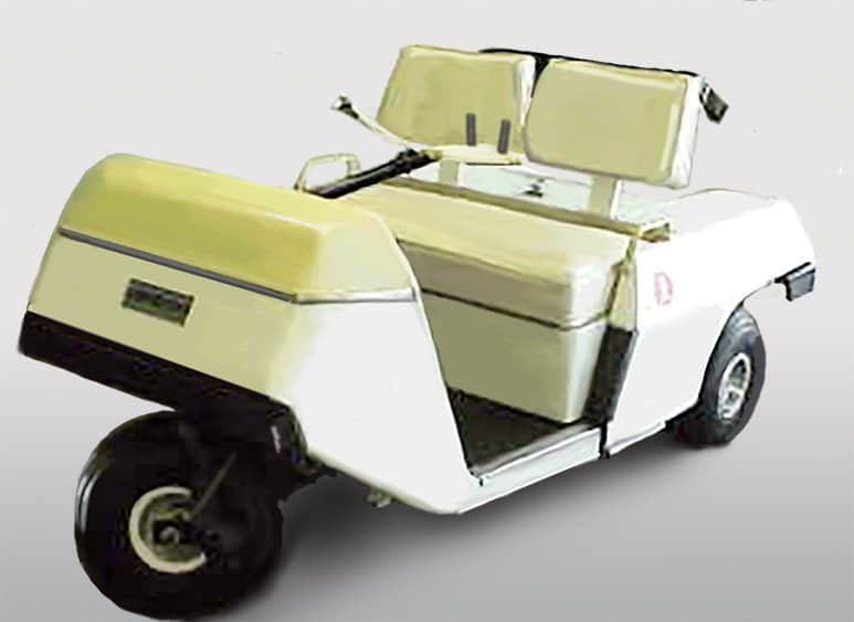
The E-Z-GO model 400 appeared with several different configurations: a 5-speed with 7 solenoids and a two-speed motor, a 3-speed with 6 solenoids, and a 4-speed with one solenoid.
Model 400B
The 400b came with a 2-speed reversible series motor with an integral speed sensing device. The use of the two-speed motor allowed less strain on the batteries by using the resistor only for a smoother startup. Forward and reverse are controlled through the key switch.
The first speed is 18 volts through low-speed motor connections, the second speed is 18 volts through the high-speed motor connections. The 3rd and 4th speeds are achieved by applying 36 volts to the previous two motor connections. The 5th speed is the “Hill Climbing Speed”. Fully depressing the pedal engages the hill-climbing mode and when the cart reaches 9 mph, the sensor in the motor switches directly to the 4th speed.
Components featured in this model are as follows:
- Two-speed, reversible, insulated, series motor with an integral speed sensing device
- 6 dual contact solenoids
- One single contact solenoid
- Single contact plunger switch
- Rotary contact foot pedal switch
- Key switch 4 forward, off, and reverse
- Reverse buzzer
- Resistor
- Charging switch
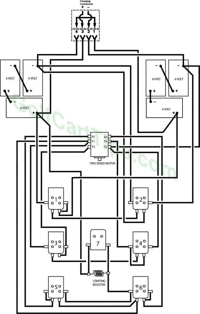
Model 400B Original Schematic

400B Heavy Cable Logic Diagram
Solenoids #1 and 2 change the operating voltage from 18 volts to 36 volts. 18 volts is used in the starting, first, and second speed. 36 volts is used for the third speed and the hill-climbing feature.
Solenoids #3 and #4 are used to switch the motor field windings from either series or parallel position. The series connection is for the starting speed, the first speed, and the third speed. The parallel connection is for the second speed and the hill-climbing mode.
Solenoids #5 and #6 are used to change the direction of the current flow and give the cart forward and reverse directions.
Solenoid #7 is the single contact solenoid and is used to bypass the resistor at all speeds except starting speed. it is strictly for smoother startup and is disengaged after the cart has begun motion.
The components shown below are arranged approximately in their position’s relationship to each other.
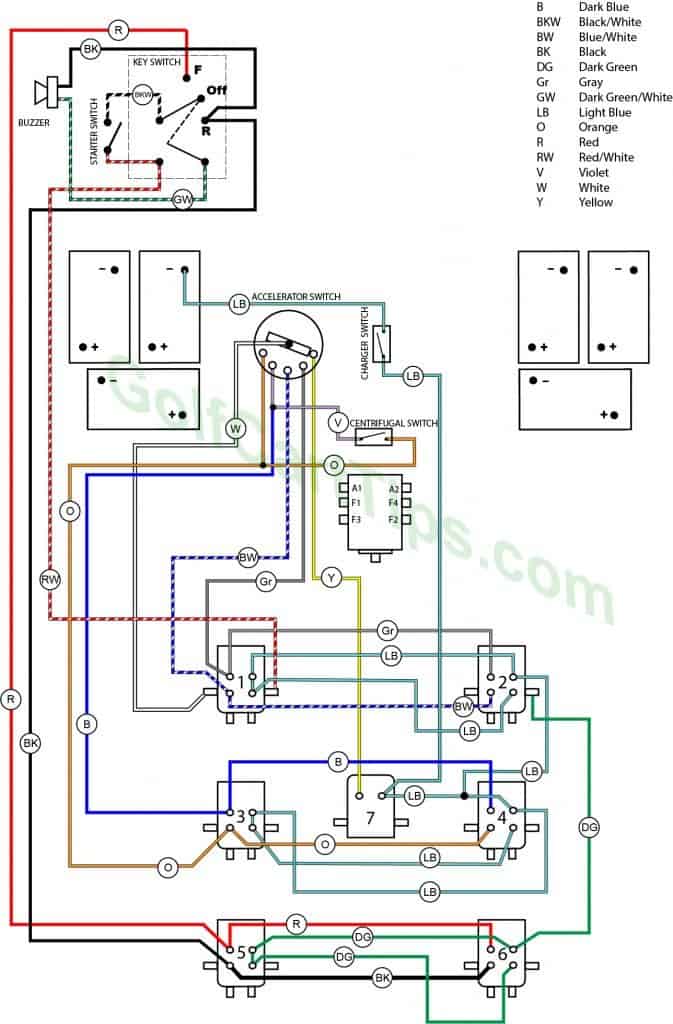
400B 16-Gauge Color Diagram
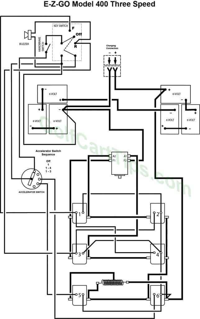
Model 400D Three Speed – 6 Solenoid
16 Gauge and Heavy Cable Layout
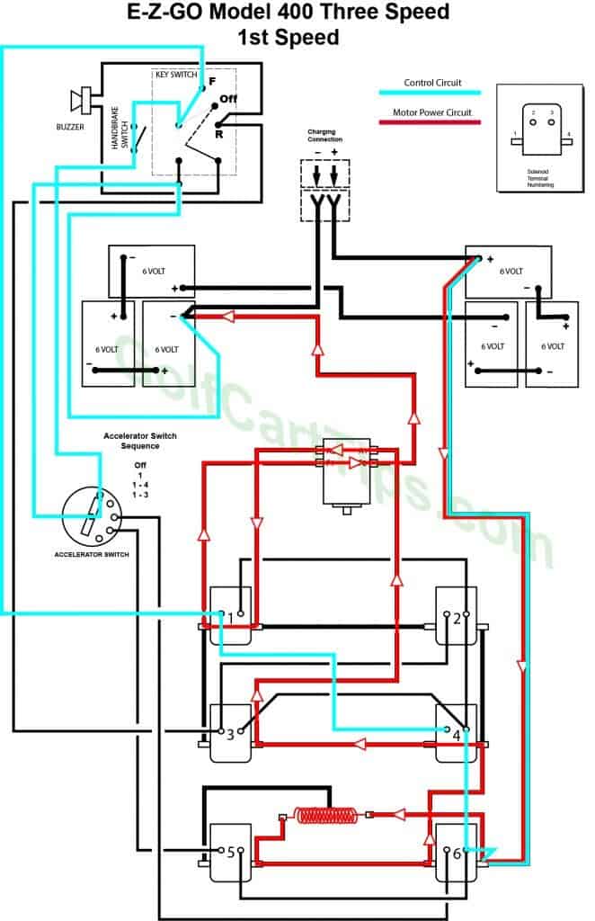
First Speed Control Diagram
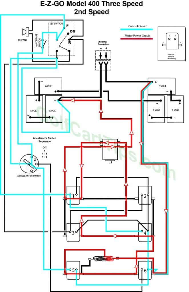
Second Speed Control Diagram
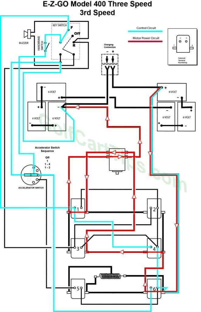
Third Speed Control Diagram
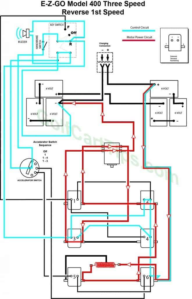
First Speed Reverse Control Diagram
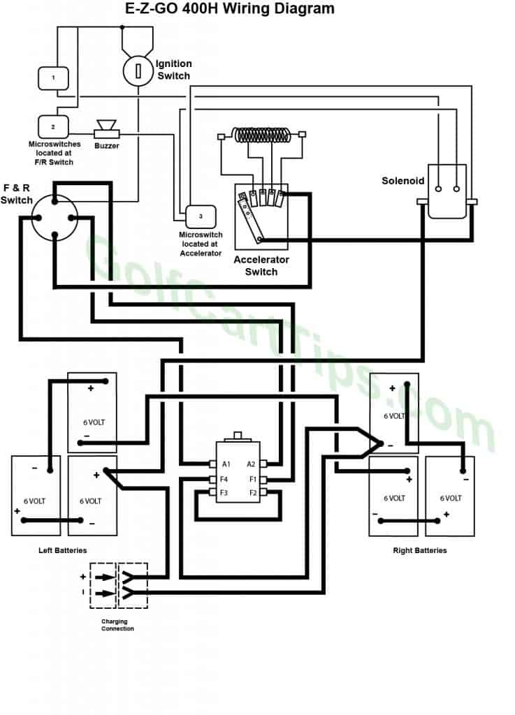
Model 400H Four Speed – 1 Solenoid
