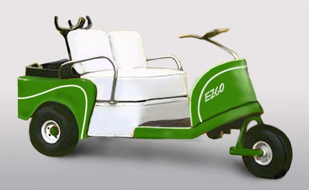
Known for its golf carts, EZGO was established on June 13, 1954. The founders were two brothers, Billy and Beverly ‘Bev’ Dolan. They started the company in a garage located in Augusta, Georgia. At its inception, EZGO focused on creating electric golf carts. These carts were powered by a surplus 24-volt military motor and a stack of 36-volt batteries.
However, it wasn’t until 1971 that EZGO decided to introduce a golf cart that ran on gasoline. Regrettably, it’s tough to find manuals for the early models from the 1950s. Also, the technical information available online is often unclear and inconsistent. Therefore, our goal is to make available clear and easy-to-understand Ezgo Wiring Diagrams 36 Volt. This information can be very useful to those who wish to refurbish classic EZGO golf carts.
Golf Cart Operation
The EZGO car is a unique vehicle that operates at top speed, using three different speeds controlled by a system of solenoids and resistors. The manufacturer recommends using the highest speed as it consumes the same or possibly less energy than the first or second speeds.
The speeds are controlled by the current from the batteries which passes through all or a part of a resistor. The whole resistor is used for low-speed, half for the second speed, and none for high-speed. This process is controlled by three solenoids, with one solenoid for each speed.
The forward-reverse switch is linked to another series of solenoids that control the current flow to the motor. In reverse, the current passes through solenoids A and B, and in forward through solenoids C and D.
When the key is turned to the right, the current passes through the black wire to solenoids C and D. Solenoid C energizes, connecting Traction Motor Terminal S1 and A2. Simultaneously, solenoid D energizes, closing a circuit between Traction Motor Terminal A1 (directed through the speed-selected solenoids 1, 2, or 3) and the battery’s positive terminal. This action is similar to bridging S1 and A2 and connecting A1 to the positive terminal and S2 to the negative terminal, causing the cart to move forward.
When the key is turned left, the current flows through the white wire to solenoids A and B. Solenoid A energizes, creating a circuit between Traction Motor Terminal S1 and A1. At the same time, solenoid B closes a circuit between Traction Motor Terminal A2 (directed through the speed-selected solenoids 1, 2, or 3) and the battery’s positive terminal. This is like bridging S1 and A1, placing A2 on the positive terminal, and S2 on the negative terminal, causing the cart to move in reverse.
This substitute charger is designed with exceptional compatibility features that allow it to work perfectly with older models of EZGo Carts. Its construction is robust and durable, ensuring it can stand up to regular use without any compromise in its performance.
The charger is easy to use and connects effortlessly to your cart, providing efficient and reliable charging every time. It serves as an excellent choice for those who own older EZGo Cart models and need a replacement or backup charger. With this substitute charger, you can keep your cart powered up and ready for use anytime, anywhere.
EZGO Late 1950’s 16 Gauge 36 Volt Battery Wiring Diagram

Wire colors on the early EZGO were almost all black or white, and a green wire for first speed. This cart is a resistor type speed control with 7 solenoids. “A” and “B” solenoids are reverse, “C” and “D” solenoids are Forward, and Solenoids 1,2, and 3 are speed controls.
EZGO Late 1950’s Heavy Cable Wiring Diagram
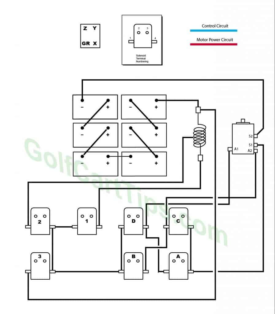
Current Flow Logic Diagrams
First Speed
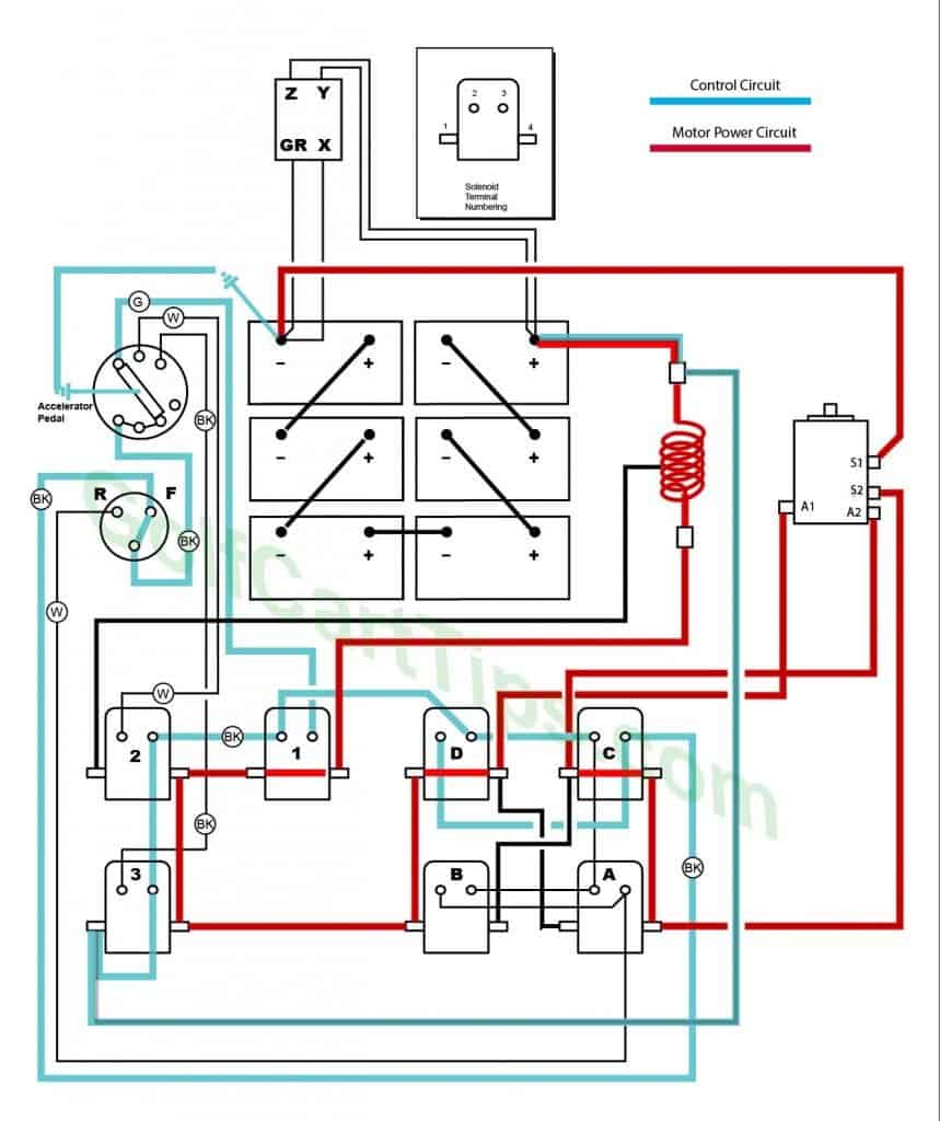
- Key switch – Forward
- Speed Switch – First Speed Contact
- Solenoid “C” Closed – Voltage applied to small terminals, continuity across large terminals
- Solenoid “D” Closed – Voltage applied to small terminals, continuity across large terminals
- Solenoid “A” Open – Voltage not applied to small terminals
- Solenoid “B” Open – Voltage not applied to small terminals
- Solenoid “1” Closed – Voltage applied to small terminals, continuity across large terminals
- Solenoid “2” Open – Voltage not applied to small terminals
- Solenoid “3” Open – Voltage not applied to small terminals
- Voltage across the full length of the Resistor 7
Second Speed
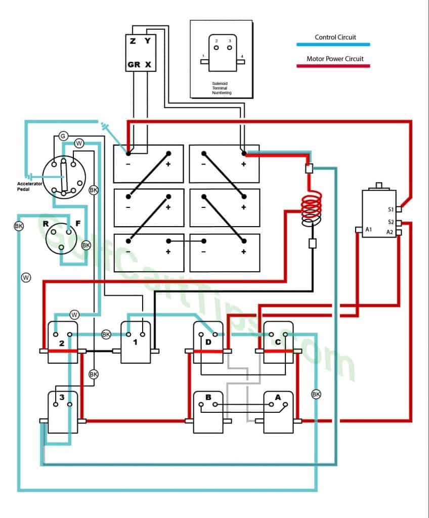
- Key switch – Forward
- Speed Switch – Second Speed Contact
- Solenoid “C” Closed – Voltage applied to small terminals, continuity across large terminals
- Solenoid “D” Closed – Voltage applied to small terminals, continuity across large terminals
- Solenoid “A” Open – Voltage not applied to small terminals
- Solenoid “B” Open – Voltage not applied to small terminals
- Solenoid “1” Open – Voltage not applied to small terminals
- Solenoid “2” Closed – Voltage applied to small terminals, continuity across large terminals
- Solenoid “3” Open – Voltage not applied to small terminals
- Voltage across half the length of the Resistor 7
Third Speed
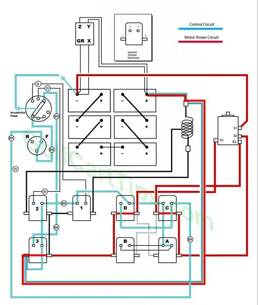
- Key switch – Forward
- Speed Switch – Third Speed Contact
- Solenoid “C” Closed – Voltage applied to small terminals, continuity across large terminals
- Solenoid “D” Closed – Voltage applied to small terminals, continuity across large terminals
- Solenoid “A” Open – Voltage not applied to small terminals
- Solenoid “B” Open – Voltage not applied to small terminals
- Solenoid “1” Open – Voltage not applied to small terminals
- Solenoid “2” Open – Voltage not applied to small terminals
- Solenoid “3” Closed – Voltage applied to small terminals, continuity across large terminals
- Voltage bypasses Resistor 7
First Speed Reverse
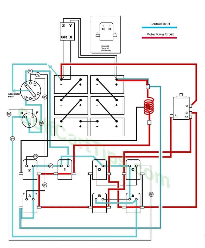
- Key switch – Reverse
- Speed Switch – First Speed Contact
- Solenoid “C” Open – Voltage not applied to small terminals
- Solenoid “D” Open – Voltage not applied to small terminals
- Solenoid “A” Closed – Voltage applied to small terminals, continuity across large terminals
- Solenoid “B” Closed – Voltage applied to small terminals, continuity across large terminals
- Solenoid “1” Closed – Voltage applied to small terminals, continuity across large terminals
- Solenoid “2” Open – Voltage not applied to small terminals
- Solenoid “3” Open – Voltage not applied to small terminals
- Voltage across the full length of the Resistor 7
Second Speed Reverse
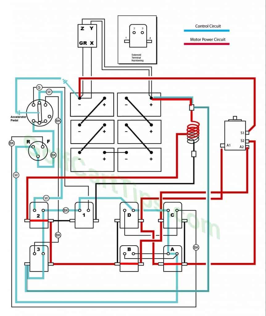
- Key switch – Reverse
- Speed Switch – Second Speed Contact
- Solenoid “C” Open – Voltage not applied to small terminals
- Solenoid “D” Open – Voltage not applied to small terminals
- Solenoid “A” Closed – Voltage applied to small terminals, continuity across large terminals
- Solenoid “B” Closed – Voltage applied to small terminals, continuity across large terminals
- Solenoid “1” Open – Voltage not applied to small terminals
- Solenoid “2” Closed – Voltage applied to small terminals, continuity across large terminals
- Solenoid “3” Open – Voltage not applied to small terminals
- Voltage across half the length of the Resistor 7
Third Speed Reverse
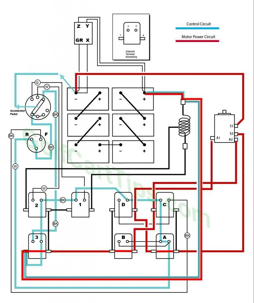
- Key switch – Reverse
- Speed Switch – Third Speed Contact
- Solenoid “C” Open – Voltage not applied to small terminals
- Solenoid “D” Open – Voltage not applied to small terminals
- Solenoid “A” Closed – Voltage applied to small terminals, continuity across large terminals
- Solenoid “B” Closed – Voltage applied to small terminals, continuity across large terminals
- Solenoid “1” Open – Voltage not applied to small terminals
- Solenoid “2” Open – Voltage not applied to small terminals
- Solenoid “3” Closed – Voltage applied to small terminals, continuity across large terminals
- Voltage bypasses Resistor 7
Wiring Key Ezgo Wiring Diagrams 36 Volt 1950’s Model 300 EZGO

- Charger Connection
- Speed Switch – 4 wires (Green, Black, White, Black) For Solenoids 1,2, and 3
- Key Switch – Black wire to Solenoid Terminal C3, Black wire to Speed Switch Common, White wire to Solenoid Terminal A3
- Batteries – (6) 6-volt
- Traction Motor
A1 – Black wire to Solenoid Terminal D4
A2 – Black wire to Solenoid Terminal C1
S1 – Black wire to Solenoid Terminal A4
S2 – Black Wire to Battery Negative Terminal - Solenoid – Single Action
Solenoid A
A1 – Black wire to Solenoid Terminal D4
A2 – Black wire to Solenoid Terminal B3, Black wire to Solenoid Terminal C2
A3 – Black wire to Solenoid Terminal B2, Black wire to Key Switch R
A4 – Black wire to Solenoid Terminal C4, Black wire to Traction Motor S1
Solenoid B
B1 – Black wire to Solenoid Terminal D1, Black wire to Solenoid Terminal 3-4
B2 – Black wire to Solenoid Terminal A3
B3 – Black wire to Solenoid Terminal A2
B4 – Black wire to Solenoid Terminal C1
Solenoid C
C1 – Black wire to Solenoid Terminal B4, Black wire to Traction Motor A2
C2 – Black wire to Solenoid Terminal D3
C3 – Black wire to Solenoid Terminal D2, Black wire to Key Switch F
C4 – Black wire to Solenoid Terminal A4
Solenoid D
D1 – Black wire to Solenoid Terminal B1
D2 – Black wire to Solenoid Terminal C3
D3 – Black wire to Solenoid Terminal 1-2, Black wire to Solenoid Terminal C2
D4 – Black wire to Solenoid Terminal A1, Black wire to Traction Motor A1
Solenoid 1
1-1 – Black wire to Solenoid Terminal 2-4
1-2 – Black wire to Solenoid Terminal 2-3, Black wire to Solenoid Terminal D3
1-3 – Green wire to Speed Switch First Speed Contact
1-4 – Black wire to Resistor 7
Solenoid 2
2-1 -Black wire to Middle Tap Resistor 7
2-2 – White wire to Key Switch Second Speed Contact
2-3 – Black wire to Solenoid Terminal 1-2, Black wire to Solenoid Terminal 3-3
2-4 – Black wire to Solenoid Termina 1-1, Black wire to Solenoid Terminal 3-4
Solenoid 3
3-1 – Black wire to Solenoid Terminal 3-3, Black wire to Bypass contact on Resistor 7
3-2 – Black wire to Speed Switch Third Speed Contact
3-3 – Black wire to Solenoid Terminal 2-3, Black wire to Solenoid Terminal 3-1
4-4 – Black wire to Solenoid Terminal 2-4, Black wire to Solenoid Terminal B1 - Resistor

