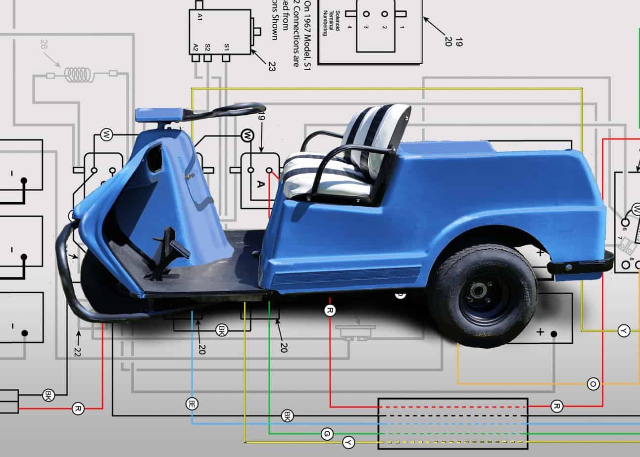
These wiring diagrams are for the final years of the Harley Davidson golf cart before the name “Harley Davidson” was dropped. These drawings are for the electric model only. Note that the designation DE-3 and DE-4 signify a 3 or 4-wheel cart.
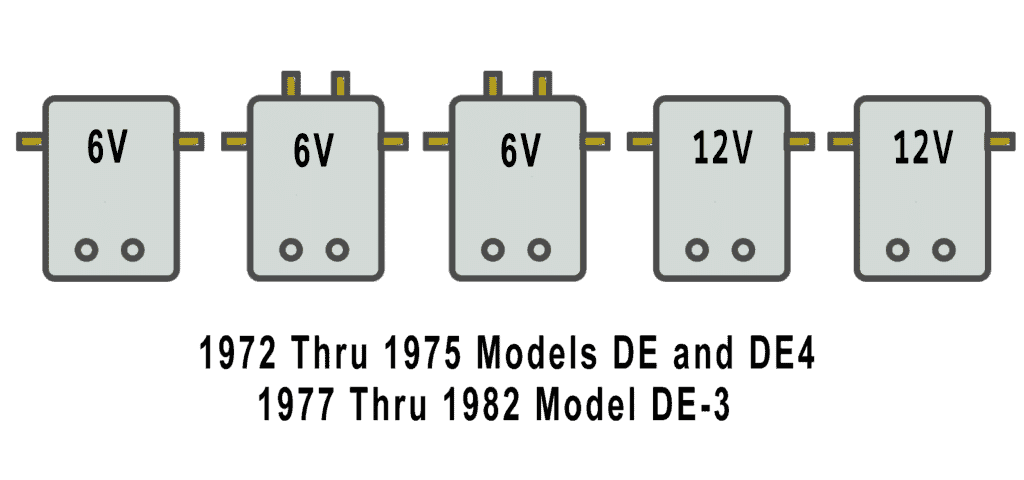
Harley Davidson Golf Cart Wiring Diagrams 1979–1982 DE, DE4 Solenoid Arrangements
1979-82 Model DE, DE-3, DE-4 Heavy Cable Diagram
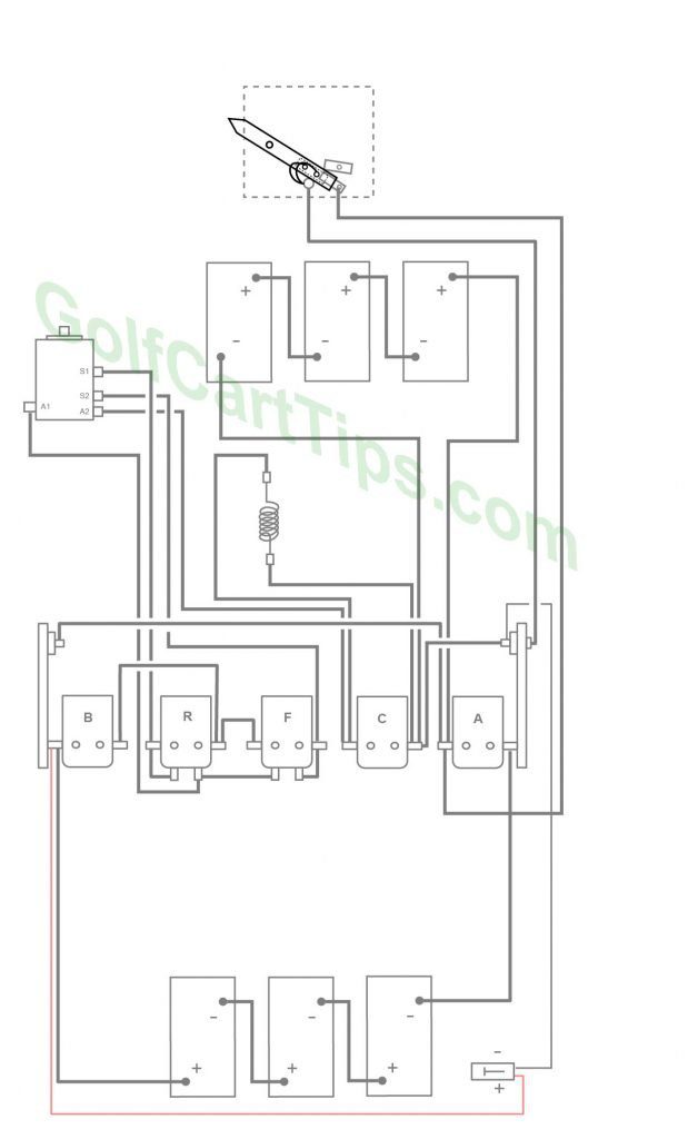
1979-82 Model DE,DE-3,DE-4 Control Circuit Wiring Diagram for 16 Gauge Wire

Wiring Key 1979-82 Model De, DE-3, DE-4
- Key Switch – 4 wires (Green, Blue, Yellow, Red) For terminals 2, 3, 4, and 5
- Key Switch Terminal – Green wire to Solenoid Terminal R2
- Key Switch Terminal – Blue wire to Solenoid Terminal F2
- Key Switch Terminal – Red wire to Solenoid Terminal B2
- Key Switch Terminal – Yellow wire to Reverse Buzzer 19
- Speed Switch (Contains Terminals 7, 8, 9, 10)
- Speed Switch Terminal – White wire to Terminal 15 on Switch Wiper Arm (2), Black wire to Right Diode 21
- Speed Switch Terminal – Black wire to Solenoid Terminal A1
- Speed Switch Terminal – Brown wire to Solenoid Terminal B3, Diode 12
- Speed Switch Terminal – White wire to Microswitch 11 Common, Diode 12
- Microswitch –NC Terminal Black wire to Solenoid Terminal C3, NO Terminal Red wire to Solenoid Terminal A2, Common Terminal White wire to Speed Switch Terminal 10
- Diode
- Front Batteries (3)
- Rear Batteries (3)
- Single Action Solenoid A, B, and C
Solenoid A
A1 – Black wire to Left Diode, Black wire to Positive Terminal Front Batteries, Black wire to Speed Switch Terminal 8
A2 – Red wire to Time Delay, Red wire to Microswitch NC Terminal
A3 – White wire to Solenoid Terminal C2, White wire to Left Diode
A4 – Orange wire to Reverse Buzzer 19, Black wire to Negative Terminal Rear Batteries Solenoid B
B1 – White wire to Solenoid Terminal R3, Black wire Positive Terminal Rear Batteries, Red wire to Charger Plug Positive
B2 – Red wire to Key Switch Terminal 4
B3 – Brown wire to Speed Switch Terminal 9
B4 – Copper Strap to Solenoid Terminal B4 Solenoid C
C1 – Black wire to Traction Motor A2, Black wire to Resistor 18
C2 – White wire to Solenoid Terminal F3, White wire to Solenoid Terminal A3
C3 – Black Wire to Microswitch NC Terminal, Black wire to Time Delay 22
C4 – Black wire to Resistor 18, Black wire to Negative Terminal Front Batteries, Black wire to Right Diode 21 - Dual Action Solenoid
Solenoid R
R1 – Black wire to Motor Terminal S1, Copper Strap to R5
R2 – Green wire to Key Switch Terminal 2
R3 – White wire to Solenoid Terminal B1, White wire to Solenoid Terminal F3
R4 – Copper Strap to Solenoid Terminal B4, Copper Strap to Solenoid Terminal F1
R5 – Copper Strap to Solenoid Terminal R1
R6 – Copper Strap to Solenoid Terminal F5, Black wire to Traction Motor Terminal A1 Solenoid F
F1 – Copper Strap to Solenoid Terminal R4
F2 – Blue wire to Key Switch Terminal 3
F3 – White wire to Solenoid Terminal R3, White wire to Solenoid Terminal C2
F4 – Copper Strap to Solenoid Terminal F6, Black wire to Motor Terminal S2
F5 – Copper Strap to Solenoid Terminal R6
F6 – Copper Strap to Solenoid Terminal F4 - Traction Motor
- Resistor
- Reverse Buzzer
- Left Diode
- Right Diode
- Time Delay
- Charger Plug
1979 – 1982 Energized Circuits Diagrams
Charging
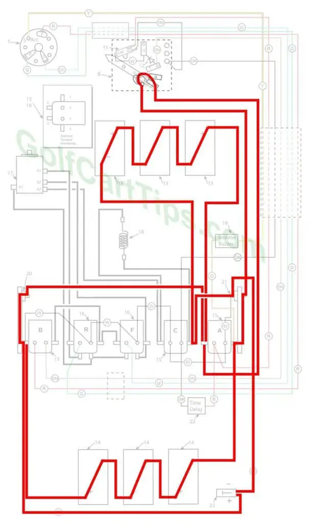
The wiper arm is at full rest and making contact with Contact Terminal #1. Batteries are in parallel through the charger plug 23.
- Key switch – Off
- Speed Switch – At Contact #1
- Solenoid “A” Open – Not Energized
- Solenoid “B” Open – Not Energized
- Solenoid “C” Open – Not Energized
- Solenoid “F” Open – Not Energized
- Solenoid “R” Open – Not Energized
- Voltage to Motor – None
- Voltage across A1 and A2 – None
- Micro Switch – In Normally Closed state
First Speed
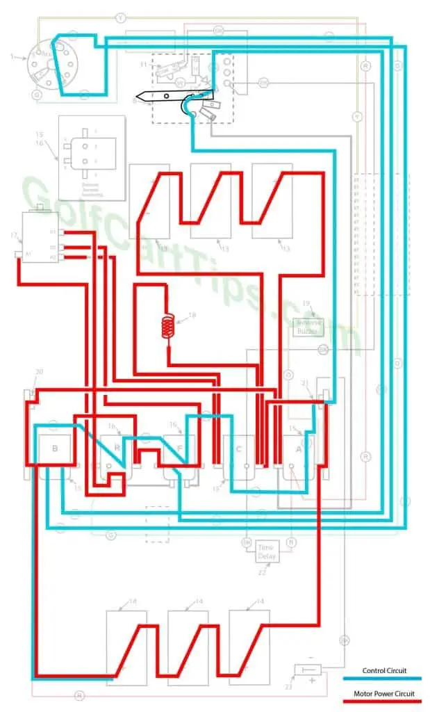
As the wiper arm moves off of Terminal #1, power is applied through the left and right diodes. Terminal #2 is a buffer and provides no connections. Contact is made with Terminal #3 and power is applied to Solenoids “F” and “B”. Power is passed through the Resistor 18 and First Speed is achieved at 18-volts parallel. The Speed Switch diode prevents Solenoid “C” from being energized from contact #3.
- Key switch – Forward
- Speed Switch – Contact with #3 Speed Terminal
- Solenoid “A” Open – Not Energized
- Solenoid “B” Closed – Voltage applied to small terminals, continuity across large terminals
- Solenoid “C” Open – Not Energized
- Solenoid “F” Closed – Voltage applied to small terminals, continuity across large terminals
- Solenoid “R” Open – Not Energized
- Micro Switch – In Normally Closed state
Second Speed
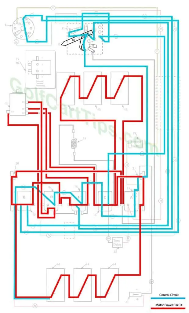
The wiper arm is now in contact with Terminal #4 and now energizes Solenoid “C”. Solenoid “C” bypasses the resistor and provides the full 18-volts to the traction motor. This is Second Speed.
- Key switch – Forward
- Speed Switch – Contact with #4 Speed Terminal
- Solenoid “A” Open – Not Energized
- Solenoid “B” Closed – Voltage applied to small terminals, continuity across large terminals
- Solenoid “C” Closed – Voltage applied to small terminals, continuity across large terminals
- Solenoid “F” Closed – Voltage applied to small terminals, continuity across large terminals
- Solenoid “R” Open – Not Energized
- Micro Switch – In Normally Closed state
Third Speed
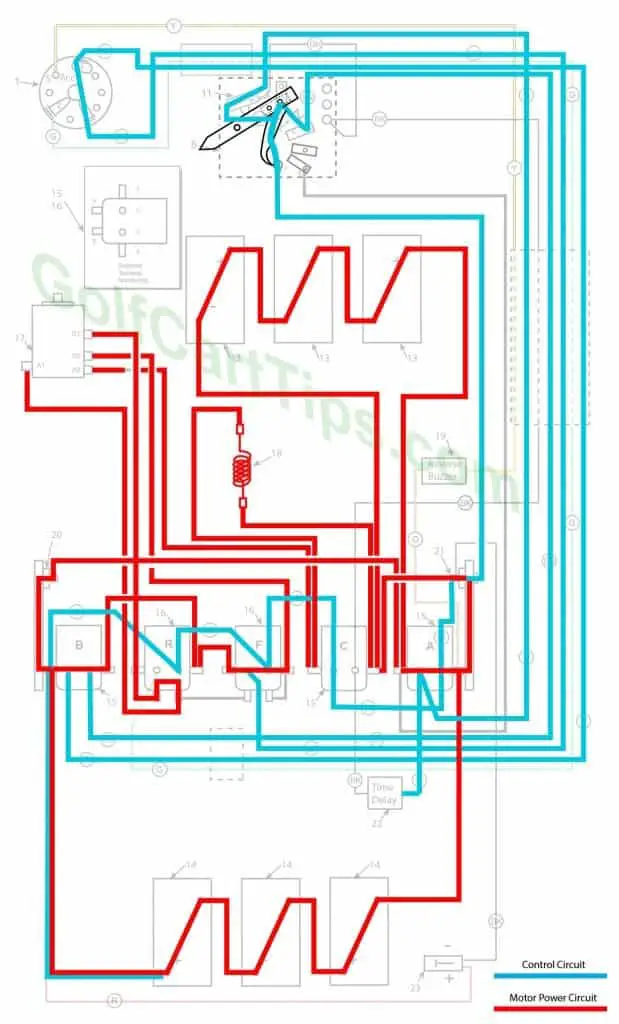
The wiper arm now reaches the maximum travel and closes the normally open contacts on the microswitch 11. This deactivates Solenoid “C” putting the resistor back into the circuit and energizes Solenoid “A”. Solenoid “A” takes the batteries out of 18-volt parallel and places it in a 36-volt series state. The Cart is now in third speed, with power now applied to the Time Delay.
- Key switch – Forward
- Speed Switch – Contact with #4 Speed Terminal and in contact with microswitch
- Solenoid “A” Closed – Voltage applied to small terminals, continuity across large terminals
- Solenoid “B” Closed – Voltage applied to small terminals, continuity across large terminals
- Solenoid “C” Open – Not Energized
- Solenoid “F” Closed – Voltage applied to small terminals, continuity across large terminals
- Solenoid “R” Open – Not Energized
- Micro Switch – In Normally Open state
Fourth Speed
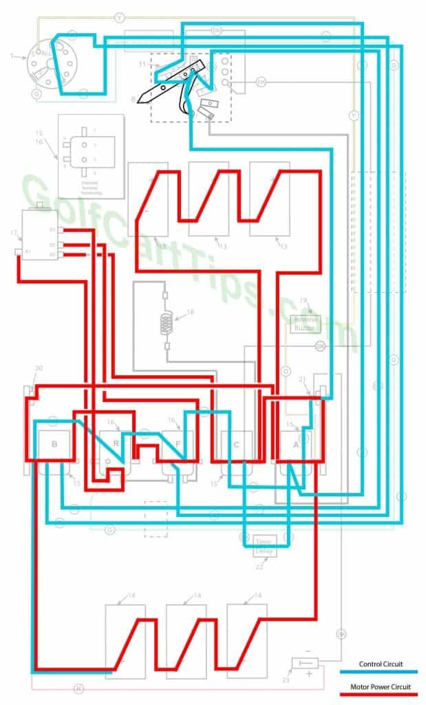
After approximately 2 seconds, the time delay kicks in and energizes Solenoid “C”, bypassing the resistor and providing a full 36-volt charge to the traction motor. This is the fourth and maximum speed.
- Key switch – Forward
- Speed Switch – Contact with #4 Speed Terminal and in contact with microswitch
- Solenoid “A” Closed – Voltage applied to small terminals, continuity across large terminals
- Solenoid “B” Closed – Voltage applied to small terminals, continuity across large terminals
- Solenoid “C” Closed – Voltage applied to small terminals, continuity across large terminals
- Solenoid “F” Closed – Voltage applied to small terminals, continuity across large terminals
- Solenoid “R” Open – Not Energized
- Micro Switch – In Normally Open state, Time Delay energized
Reverse (First Speed only is shown)
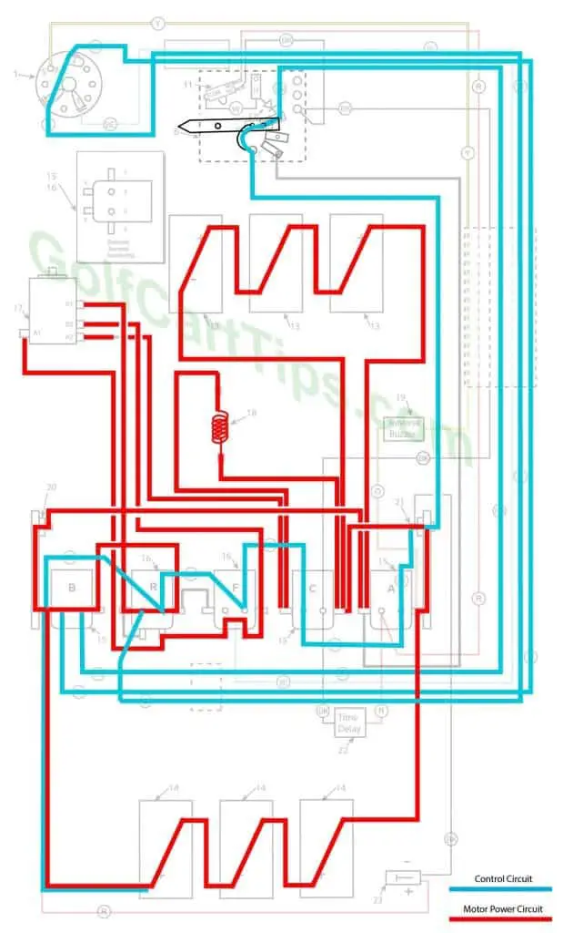
The Key Switch is set to “REV” and activates Solenoid “R”. Solenoid “R” reverses S1 and S2 connections and the Traction motor turns in the opposite direction. All other solenoid functions remain the same through the four speeds.
- Key switch – Forward
- Speed Switch – Contact with #3 Speed Terminal
- Solenoid “A” Open – Not Energized
- Solenoid “B” Closed – Voltage applied to small terminals, continuity across large terminals
- Solenoid “C” Open – Not Energized
- Solenoid “F” Open – Not Energized
- Solenoid “R” Closed – Voltage applied to small terminals, continuity across large terminals
- Micro Switch – In Normally Open state, Time Delay closed
Troubleshooting Chart for the 1979–1982 DE, DE4
| Symptom | Possible Cause | Remedy |
|---|---|---|
| Batteries will not charge | Accelerator pedal not at rest position and wiper arm is not completely on the first contact block | Refer to Speed Switch Adjustment Section here |
| Corroded or loose battery connections | Check, clean and tighten connections | |
| Faulty Battery | Test each Battery while completely disconnected from the series | |
| Faulty Charger | Use multimeter and test output voltage | |
| Will not go in forward or reverse | Faulty batteries or connections | Inspect batteries and clean connections |
| Faulty key switch | Test key switch with continuity tester | |
| Faulty speed switch | Check speed switch connections | |
| Solenoid "B" not energizing | Check cabling to Solenoid "B" Test solenoid with procedure listed here |
|
| Faulty Motor | Follow Motor trouble shooting procedures | |
| Forward Works, no reverse | Faulty key switch | Test key switch with continuity tester |
| Solenoid "R" not energizing | Check cabling to Solenoid "R" Test solenoid with procedure listed here |
|
| Solenoid "F" open between Large bottom terminals | Check connections to Solenoid "B" large terminals. Test solenoid with procedure listed here |
|
| Reverse works OK, no Forward | Faulty key switch | Test key switch with continuity tester |
| Solenoid "R" open circuit on large bottom terminals | Check connections to Solenoid "R" large terminals. Test solenoid with procedure listed here |
|
| Solenoid "F" not Energizing | Check connections to Solenoid "F" control terminals. Test solenoid with procedure listed here |
|
| Speed 1 Works, no 2, 3, or 4 | Speed Switch wiper arm not making contact with 4th speed contact pad. | Remove and inspect Speed Switch. |
| Speed Switch diode open | Check diode leads. | |
| Speed 1 and 2 Works, no 3, or 4 | Micro switch not making the connection between NC and COM | Test Micro Switch |
| Solenoid "A" not energizing, stuck open | Check connections to Solenoid "A" terminals. Test solenoid with procedure listed here |
|
| Speed 3 and 4 Works, no 1 or 2 | Both Motor diodes open | Check diode condition |
| Solenoid "A" stuck closed | Check connections to Solenoid "A" control terminals. Test solenoid with procedure listed here |
|
| Speed 3 and 4 works, no 1, or 2 | Short in Speed Switch Diode | Inspect, repair, or replace. |
| Speed 2 and 4 works, no 1 or 3 | Solenoid "C" stuck closed bypassing Resistor | Test solenoid "C" with procedure listed here |
| Open Resistor | Check Resistor connections. | |
| Speed 1 and 3 works, no 2 or 4 | Solenoid "C" not energizing or stuck open passing all current through Resistor | Test solenoid "C" with procedure listed here |
| Speed 1 and 4 works, no 2 or 3 | Time Delay Tube shorted | Check Time Delay Tube connections. |
| Speed 1, 2, and 3 works, no 4 | Time Delay Tube open or faulty | Check Time Delay Tube connections. |
| Speed 3 has a long delay or too short of a delay | Time Delay Tube open faulty | Test Time Delay Tube. |
| Front set of batteries goes dead or Rear set of batteries goes dead | One Motor Diode is open | Check connections to Motor Diode or replace. |
Other Years and Models for The Harley Davidson Golf Cart

