
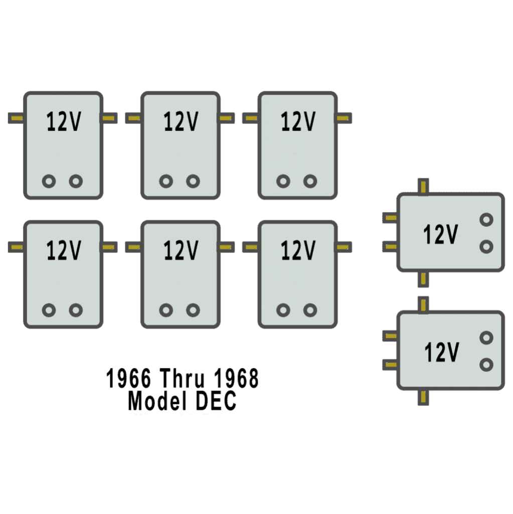
The DEC differs from the DE model with the addition of headlights, taillights, and a horn. The High Range/Low Range capability was available in the 1966 through 1968 DEC.
The Harley Davidson Golf Cart was manufactured from 1963 through 1982 and came in models DE, DEC, DEF, DE-3, and DE-4
Troubleshooting Harley Davidson Golf Carts DEC
Troubleshooting Harley Davidson Golf Carts DEC can be a complex task, but it’s necessary for maintaining the performance and longevity of the vehicle. This process involves diagnosing the issues, which could range from engine problems to electrical system malfunctions.
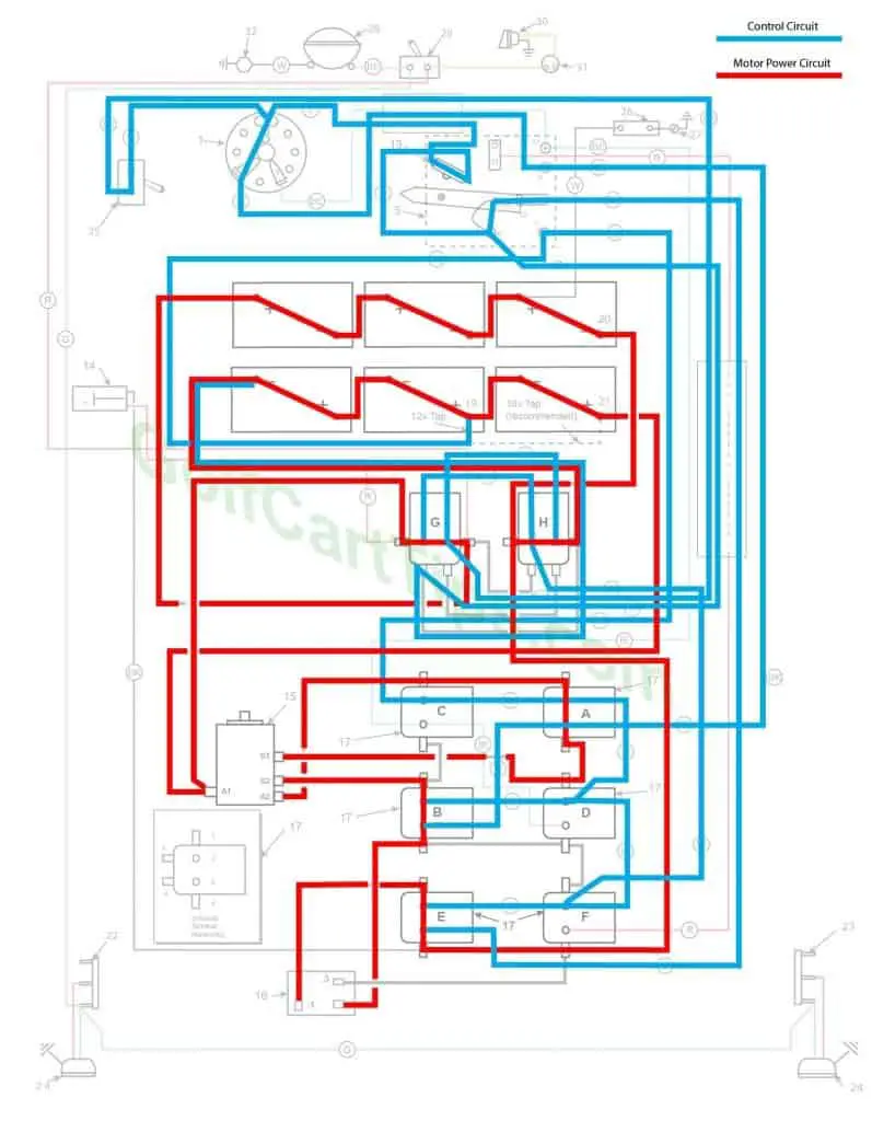
1966-67 Model DEC Heavy Cable Diagram
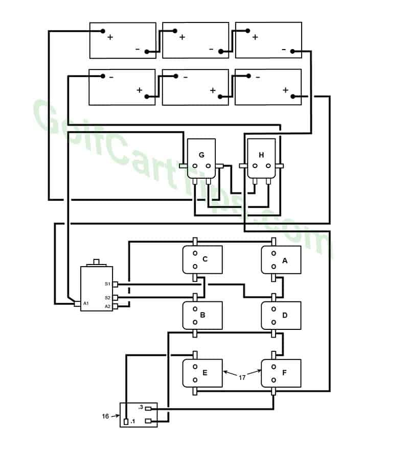
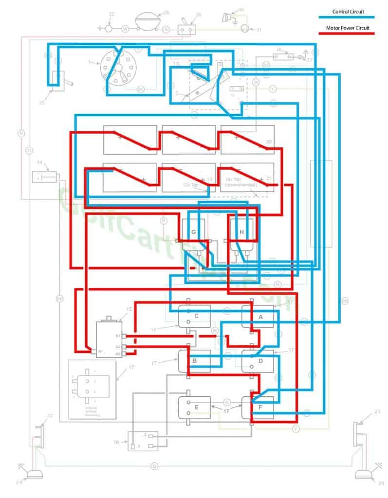
1966-67 Model DEC 16 Gauge Cable Diagram
The above diagram is correct for the 1966 and 1967 model DEC. The 1966 model changed from a belt drive to a direct drive axle requiring the motor to rotate in the opposite direction from the prior models. The key switch connections changed so that REV becomes FWD for solenoids A and B and FWD becomes REV for solenoids C and D.
1966-67 Model DEC Charging
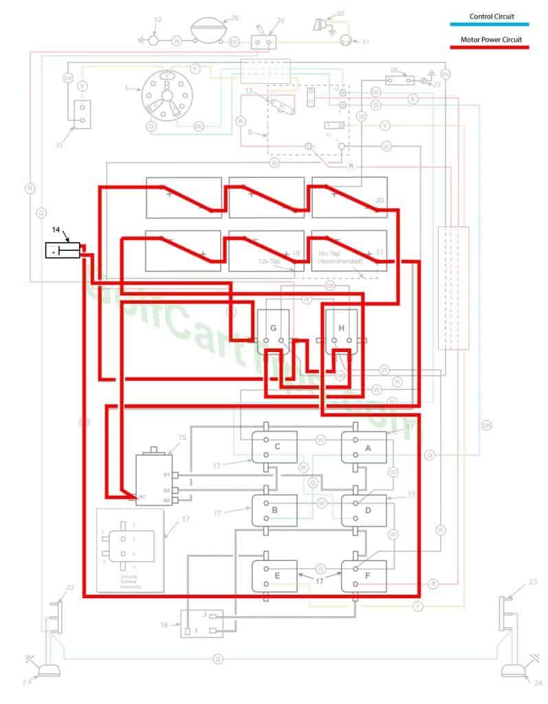
- Key switch – Off
- Speed Switch – at resting stop
- Solenoid “A” Open – Voltage not applied to small terminals
- Solenoid “B” Open – Voltage not applied to small terminals
- Solenoid “C” Open – Voltage not applied to small terminals
- Solenoid “D” Open – Voltage not applied to small terminals
- Solenoid “E” Open – Voltage not applied to small terminals
- Solenoid “F” Open – Voltage not applied to small terminals
- Solenoid “G” Open – Voltage not applied to small terminals – Lower contacts closed and bridging
- Solenoid “H” Open – Voltage not applied to small terminals – Lower contacts closed and bridging
- Voltage to Motor – None
- Voltage across A1 and A2 – None
- Micro Switch – Open
1966-67 Model DEC First Speed High Range
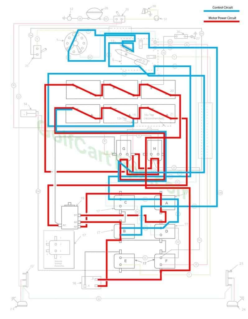
High Range – 36 volts – 6 batteries in series
- Key Switch – FWD
- Speed Switch – Moved off of resting stop – Not in contact with terminal 8 yet
- Solenoid “A” Energized – Continuity between large terminals
- Solenoid “B” Energized – Continuity between Large terminals – Voltage redirected through full resistor
- Solenoid “C” Open – Voltage not applied to small terminals
- Solenoid “D” Open – Voltage not applied to small terminals
- Solenoid “E” Open – Voltage not applied to small terminals
- Solenoid “F” Open – Voltage not applied to small terminals
- Solenoid “G” Open – Voltage not applied to small terminals – Lower contacts closed and bridging
- Solenoid “H” Open – Voltage not applied to small terminals – Lower contacts closed and bridging
- Voltage to Motor – Present
- Voltage across A1 and A2 – Present
- Micro Switch – Closed
1966-67 Model DEC Second Speed High Range
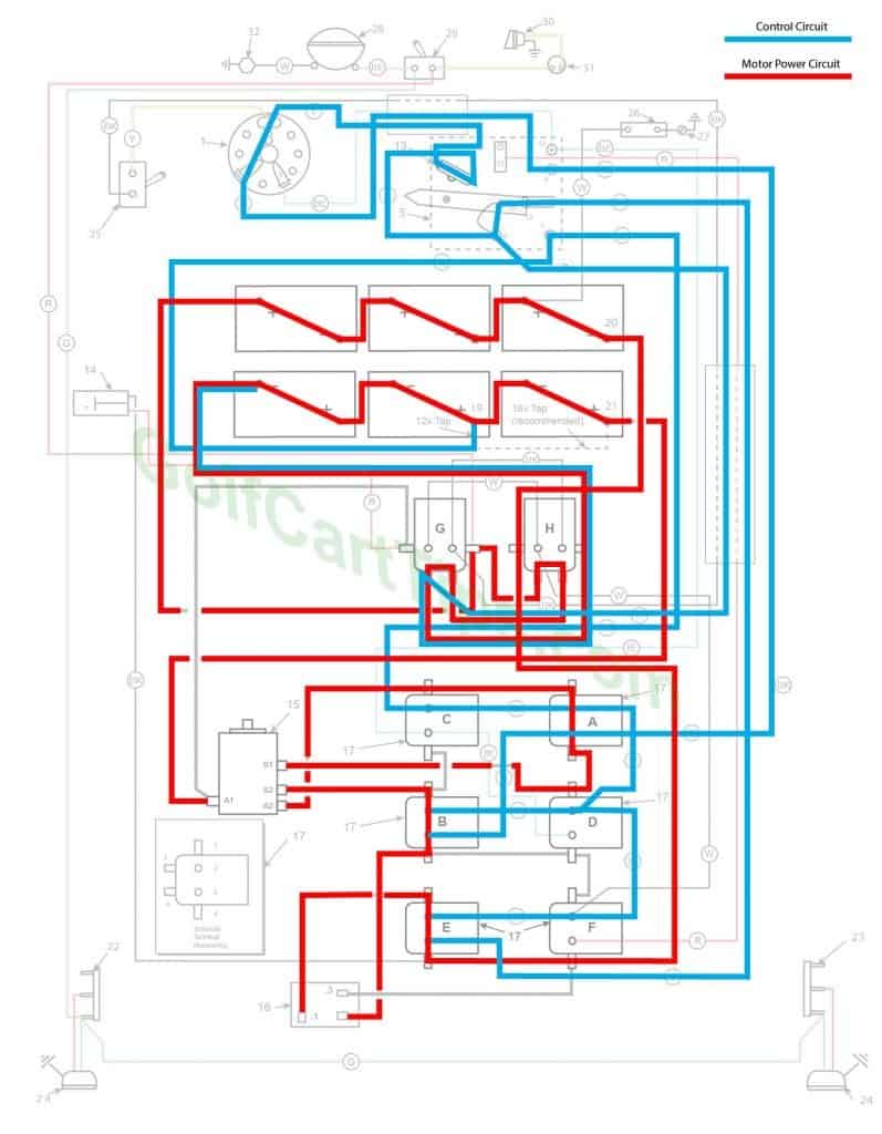
High Range – 36 volts – 6 batteries in series
- Key switch – FWD
- Speed Switch – at Terminal 8
- Solenoid “A” Energized – Continuity between large terminals
- Solenoid “B” Energized – Continuity between Large terminals
- Solenoid “C” Open – Voltage not applied to small terminals
- Solenoid “D” Open – Voltage not applied to small terminals
- Solenoid “E” Energized – Continuity between large terminals – Voltage redirected through middle tap on resistor
- Solenoid “F” Open – Voltage not applied to small terminals
- Solenoid “G” Open – Voltage not applied to small terminals – Lower contacts closed and bridging
- Solenoid “H” Open – Voltage not applied to small terminals – Lower contacts closed and bridging
- Voltage to Motor – Present
- Voltage across A1 and A2 – Present
- Micro Switch – Closed
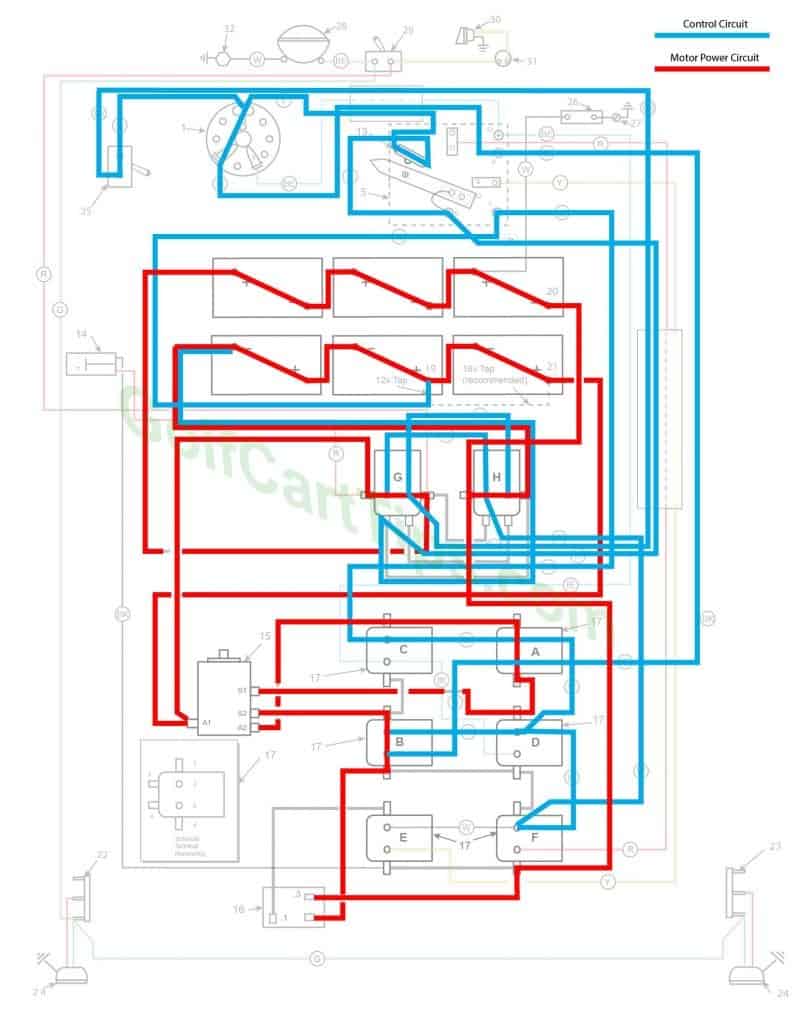
1966-67 Model DEC Third Speed High Range

High Range – 36 volts – 6 batteries in series
- Key Switch – FWD
- Speed Switch – at Teminal 11
- Solenoid “A” Energized – Continuity between large terminals
- Solenoid “B” Energized – Continuity between large terminals
- Solenoid “C” Open – Voltage not applied to small terminals
- Solenoid “D” Open – Voltage not applied to small terminals
- Solenoid “E” Open – Voltage not applied to small terminals
- Solenoid “F” Energized – Continuity between large terminals – Voltage bypassing resistor
- Solenoid “G” Open – Voltage not applied to small terminals – Lower contacts closed and bridging
- Solenoid “H” Open – Voltage not applied to small terminals – Lower contacts closed and bridging
- Voltage to Motor – Present
- Voltage across A1 and A2 – Present
- Micro Switch – Closed
1966-67 Model DEC First Speed Low Range
Low Range – 18 volts – 2 sets of batteries in parallel
- Key Switch – FWD
- Speed Switch – Moved off of resting stop – Not in contact with terminal 8 yet
- Solenoid “A” Energized – Continuity between large terminals
- Solenoid “B” Energized – Continuity between Large terminals – Voltage redirected through full resistor
- Solenoid “C” Open – Voltage not applied to small terminals
- Solenoid “D” Open – Voltage not applied to small terminals
- Solenoid “E” Open – Voltage not applied to small terminals
- Solenoid “F” Open – Voltage not applied to small terminals
- Solenoid “G” Energized – Continuity between upper large terminals placing batteries in parallel- Lower contacts open
- Solenoid “H” Energized – Continuity between upper large terminals placing batteries in parallel- Lower contacts open
- Voltage to Motor – Present
- Voltage across A1 and A2 – Present
- Micro Switch – Closed
1966-67 Model DEC Second Speed Low Range
Low Range – 18 volts – 2 sets of batteries in parallel
- Key switch – FWD
- Speed Switch – at Terminal 8
- Solenoid “A” Energized – Continuity between large terminals
- Solenoid “B” Energized – Continuity between Large terminals
- Solenoid “C” Open – Voltage not applied to small terminals
- Solenoid “D” Open – Voltage not applied to small terminals
- Solenoid “E” Energized – Continuity between large terminals – Voltage redirected through middle tap on resistor
- Solenoid “F” Open – Voltage not applied to small terminals
- Solenoid “G” Energized – Continuity between upper large terminals placing batteries in parallel- Lower contacts open
- Solenoid “H” Energized – Continuity between upper large terminals placing batteries in parallel- Lower contacts open
- Voltage to Motor – Present
- Voltage across A1 and A2 – Present
- Micro Switch – Closed
1966-67 Model DEC Third Speed Low Range
Low Range – 18 volts – 2 sets of batteries in parallel
- Key Switch – FWD
- Speed Switch – at Teminal 11
- Solenoid “A” Energized – Continuity between large terminals
- Solenoid “B” Energized – Continuity between large terminals
- Solenoid “C” Open – Voltage not applied to small terminals
- Solenoid “D” Open – Voltage not applied to small terminals
- Solenoid “E” Open – Voltage not applied to small terminals
- Solenoid “F” Energized – Continuity between large terminals – Voltage bypassing resistor
- Solenoid “G” Energized – Continuity between upper large terminals placing batteries in parallel- Lower contacts open
- Solenoid “H” Energized – Continuity between upper large terminals placing batteries in parallel- Lower contacts open
- Voltage to Motor – Present
- Voltage across A1 and A2 – Present
- Micro Switch – Closed
1966-67 Model DEC Reverse (First Speed Low Range Shown Only)
Low Range – 18 volts – 2 sets of batteries in parallel
- Key switch – REV
- Speed Switch – at Terminal 8
- Solenoid “A” Open – Voltage not applied to small terminals
- Solenoid “B” Open – Voltage not applied to small terminals
- Solenoid “C” Energized – Continuity between large terminals – S1 and S2 now reversed in polarity
- Solenoid “D” Energized – Continuity between large terminals – Voltage redirected through full resistor
- Solenoid “E” Open – Voltage not applied to small terminals
- Solenoid “F” Open – Voltage not applied to small terminals
- Solenoid “G” Energized – Continuity between upper large terminals placing batteries in parallel- Lower contacts open
- Solenoid “H” Energized – Continuity between upper large terminals placing batteries in parallel- Lower contacts open
- Voltage to Motor – Present
- Voltage across A1 and A2 – Present
- Micro Switch – Closed
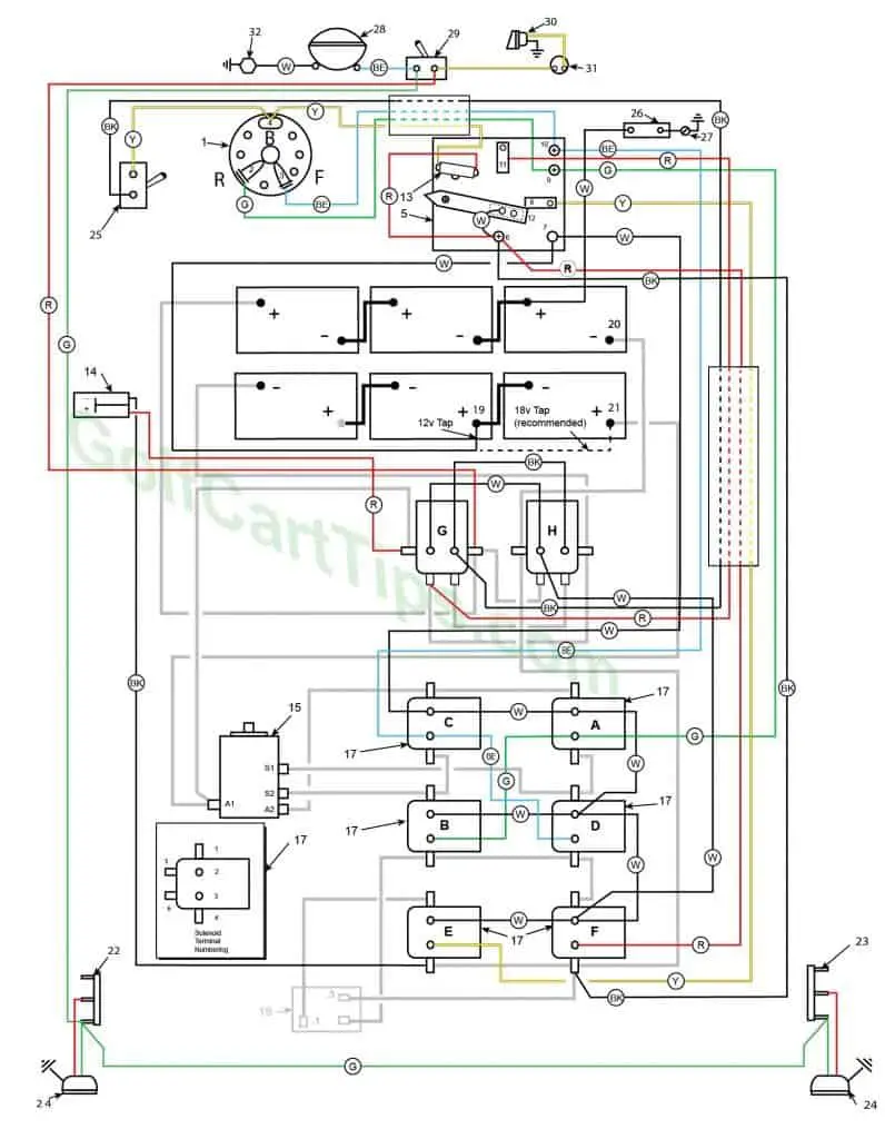
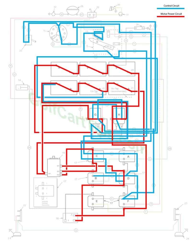
1968 Model DEC 16 Gauge Cable Diagram
1968 Model DEC Heavy Cable Diagram
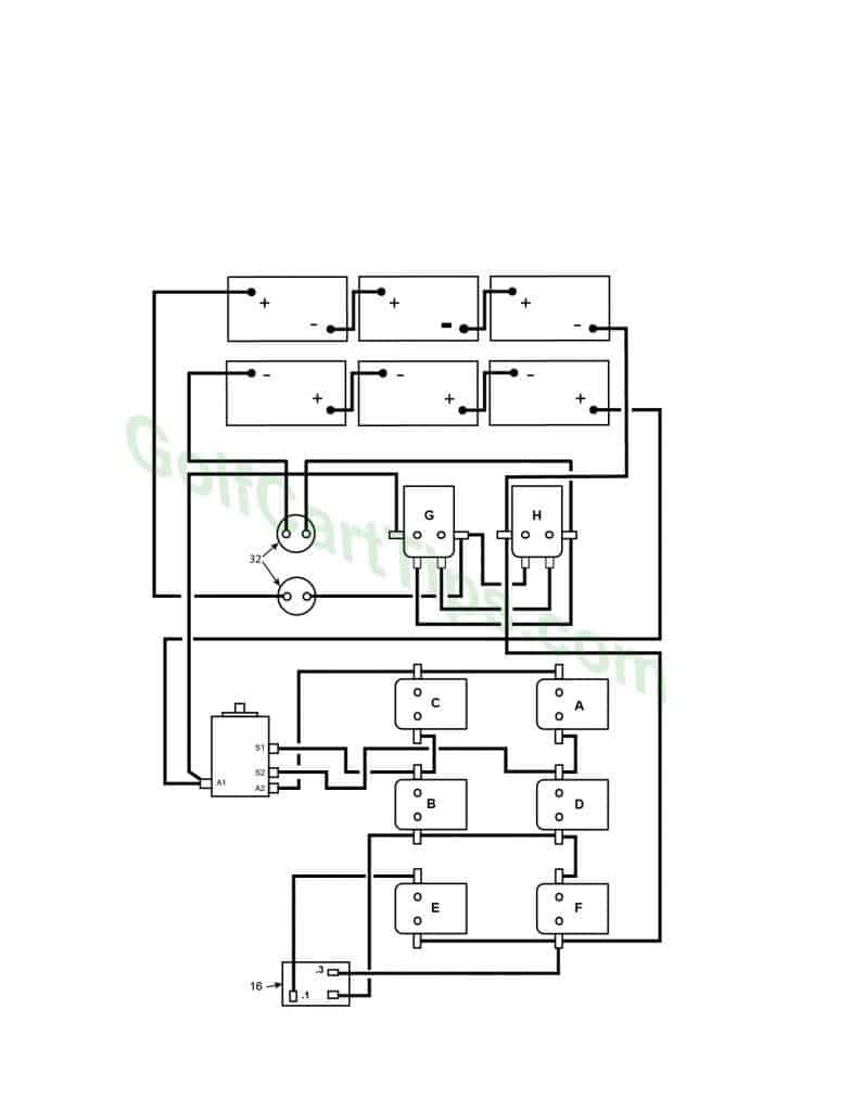
Differences in the 1966-67 Heavy Cable Diagram and the 1968 Heavy Cable Diagram is the addition of two (2) Circuit Breakers (Item 32), Motor Terminal S1 and S2 Reverse Connections.
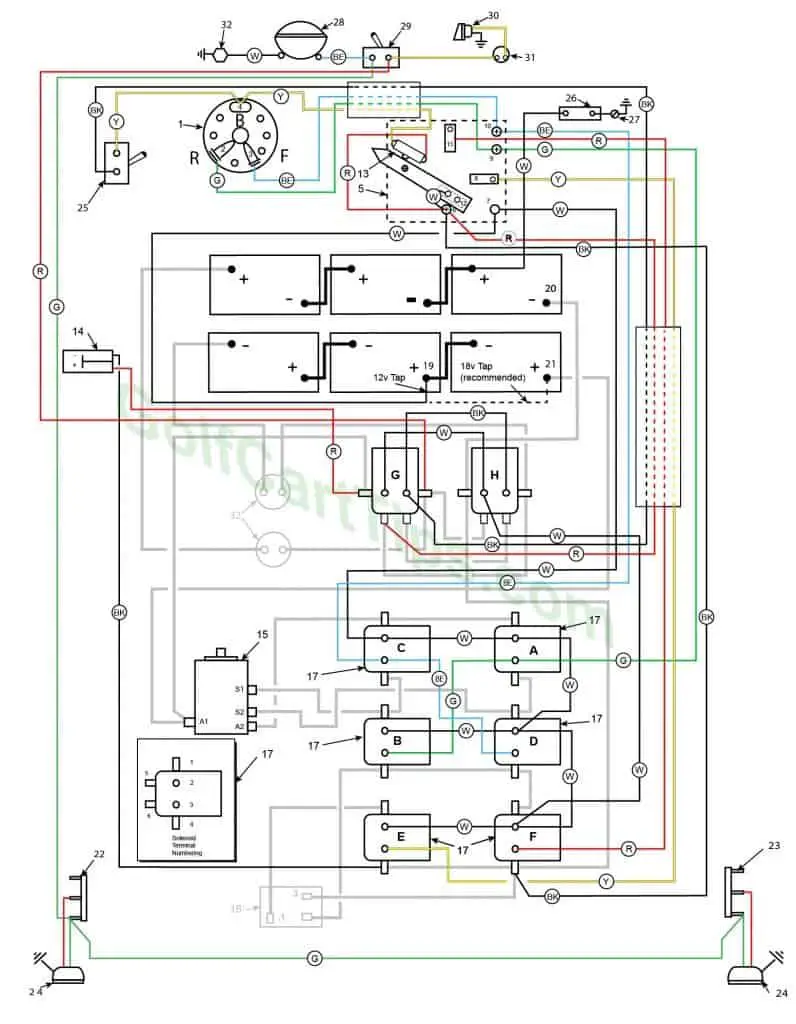
Numbering Key for 1966 -1968 Diagrams
- Key Switch – 3 wires (Green, Blue, Yellow) For terminals 2, 3, and 4
- Key Switch Terminal – Green wire to Speed Switch Connection 9
- Key Switch Terminal – Blue wire to Speed Switch Connection 10
- Key Switch Terminal – Yellow wire to Micro Switch 13, Yellow wire to Speed Selector Switch 25
- Speed Switch (Contains Terminals 6, 7, 8, 9, 10, 11, and 12)
- Speed Switch Terminal – White wire to Terminal 12 on Switch Arm, Red wire to Micro Switch, Red wire to Solenoid Terminal G5 – 3 wires
- Speed Switch Terminal – White wire to 12v Tap on battery, White wire to Solenoid Terminal C2
- Speed Switch Terminal – Yellow wire to Solenoid Terminal E3
- Speed Switch Terminal – Green wire to Key Switch Terminal 2 and Green wire to Solenoid Terminal A3
- Speed Switch Terminal – Blue wire to Key Switch Terminal 3 and Blue wire to Solenoid Terminal C3
- Speed Switch Terminal – Red wire to Solenoid Terminal F3
- Speed Switch Arm Terminal – White wire jumper to Speed Switch Terminal 6
- Micro Switch – Yellow wire to Key Switch Terminal 4 and Red wire to Speed Switch Terminal 6
- Charger Connection Plug – Negative Terminal 1 Black wire to Speed Switch Terminal E4 and Positive Terminal 2 Red wire to Solenoid Terminal G1
- Motor – 5 wires
A1 – Black wire to Solenoid Terminal G1, Black wire to Right Rear Battery Positive Terminal
A2 – Black wire to Solenoid Terminal C1
S1 – Black Wire to Solenoid Terminal D1 (or to Solenoid Terminal B1 1968 Model only)
S2 – Black Wire to Solenoid Terminal B1 (or to Solenoid Terminal D1 1968 Model only) - Resistor – 3 wires
Terminal .1 – Black wire to Solenoid Terminal E1
Terminal .3 – Black wire to Solenoid Terminal F4
Unmarked Terminal – Black wire to Solenoid Terminal B4 - Solenoids A, B, C, D, E, F, G, and H
Solenoid A -Located top left (front of the cart)
A1 – Copper strap to Solenoid Terminal C1
A2 – White wire to Solenoid Terminal C2 and White wire to Solenoid Terminal D2
A3 -Green wire to Speed Switch Terminal 9 and Green wire to Solenoid Terminal B3
A4 – Copper Strap to Solenoid Terminal D1Solenoid B – Located bottom center
B1 – Copper Strap to Solenoid Terminal C4, Black wire to Motor Terminal S2 (or Motor Terminal S1 1968 Model only)
B2 – White wire to Solenoid Terminal D2
B3 – Green wire to Solenoid Terminal A3
B4 – Copper Strap to Solenoid Terminal D4, Black wire to unmarked Resistor TerminalSolenoid C – Located bottom Left (front of the cart)
C1 – Copper Strap to Solenoid Terminal A1, Black wire to Motor Terminal A2
C2 – White wire to Solenoid Terminal A2, White wire to Speed Switch Terminal 7
C3 – Blue wire to Solenoid Terminal D3, Blue wire to Speed Switch Terminal 10
C4 – Copper Strap to Solenoid Terminal B1Solenoid D – Located top center
D1 – Copper Strap to A4, Black wire to Motor Terminal S1 (or Motor Terminal S@ 1968 Model only)
D2 – White wire to Solenoid Terminal F2, White wire to Solenoid Terminal B2, White wire to Solenoid Terminal A2
D3 – Blue wire to Solenoid Terminal C3
D4 – Copper Strap to Solenoid Terminal F1, Copper Strap to Solenoid Terminal B4Solenoid E – Located bottom right (rear of the cart)
E1 – Black wire to Resistor Terminal .1
E2 – White wire to Solenoid Terminal F2
E3 – Yellow wire to Speed Switch Terminal 8
E4 – Copper Strap to Solenoid Terminal F4, Black wire to Charger Negative Terminal Solenoid F – Located top right (rear of the cart)
F1 – Copper Strap to Solenoid Terminal D4
F2 – White wire to Solenoid Terminal E2, White wire to Solenoid Terminal D2
F3 – Red wire to Speed Switch Terminal 11
F4 – Copper Strap to Solenoid Terminal E4, Black wire to Solenoid Terminal H1, Black wire to .3 Resistor Terminal, Black Wire to Speed Switch Terminal 6 Solenoid G – Left side of Solenoid Plate
G1 – Red wire to Pin 1 of Charger Plug, Black wire to Motor Terminal A1
G2 – White wire to Solenoid Terminal H2
G3 – Black wire to Solenoid Terminal H3, Black wire to Speed Selector Switch
G4 – Red wire to Light Switch, Black wire to Left Front Battery Positive Terminal (or to Circuit Breaker #1 Terminal 1 1968 Model only), Black wire to Solenoid Terminal H5
G5 – Black wire to Solenoid Terminal H4, Red wire to Speed Switch Terminal 11
G6 – Black wire to Solenoid Terminal H6Solenoid H (Speed Control Solenoid) – Left Side of Solenoid Plate
H1 – Black wire to Solenoid Terminal F4, Black wire to Front Right Battery Negative Terminal 20
H2 – White wire to Solenoid Terminal G2, White wire to Solenoid Terminal F2
H3 – Black wire to Solenoid Terminal G3
H4 – Black wire to Solenoid Terminal G5, Black wire to Rear Left Battery Negative Terminal (or to Circuit Breaker #2 Terminal 1 1968 Model only)
H5 – Black wire to Solenoid Terminal G4
H6 – Black wire to Solenoid Terminal G6 - Front Batteries (6 6-volt in series to give a total of 36-volts. Includes tap for 12 or 18-volts for the solenoid circuit. (see the dashed area at front batteries)
- Center Rear Battery Positive Terminal 12v Tap, White wire to Speed Switch Terminal 7
- Right Front Battery Negative Terminal – Black wire to Solenoid Terminal H1
- Right Rear Battery Positive Terminal – 18v Tap, Black wire to Motor Terminal A1
- Left Terminal Board – Green wire to Right Terminal Board 23, Green wire to Light Switch 29, Red wire to Left Tail Light
- Right Terminal Board – Green wire to Right Terminal Board 23, Green wire to Right Taillight, Green wire to Left Tail Light, Red wire to Right Tail Light
- Tail Light – Green wire to Terminal board 23, Red wire to Terminal Board 23
- Speed Selector Switch – Black wire to Solenoid Termina G3, Yellow wire to Key Switch Terminal 4
- Fuse – White wire to Right Front Battery Positive Terminal, wire to Solenoid Plate Screw 27
- Solenoid Plate Screw – wire to Fuse 26
- Headlight – White wire to Ground Bolt 32, Blue Wire to Light Switch 29
- Light Switch – Blue wire to Headlight 28, Red wire to Solenoid Termina G4, Green wire to Left Terminal Board 22, Yellow wire to Horn Button 31
- Horn – Yellow Wire to Horn Button 31
- Horn Button – Yellow wire to Light Switch, Yellow wire to Horn 30
- Circuit Breakers (2) (1968 Model DEC only) G5
1966 Through 1968 Models DE and DEC Troubleshooting Chart
| Symptom | Possible Cause | Remedy |
|---|---|---|
| Batteries Run Down Rapidly | ||
| Batteries not charging fully | Bad Battery | Test battery cells |
| Low Electrolyte Level | Refill cells with electrolyte | |
| Bad Charging Circuit | Inspect terminals and connections for looseness and corrosion | |
| Bad Charger | Use multimeter and test output voltage | |
| Battery Drain other than use | Corrosion | Inspect battery and speed switch contacts and clean where needed |
| Loose Connections | Tighten all terminals and connections | |
| Shorts in the Circuit | Check for frayed wires touching other terminals or debris shorting contacts | |
| Faulty Motor | Go through the motor testing procedures | |
| Drag or Resistance | Brakes tight | Adjust brakes |
| Low Tire Pressure | Fill tires to recommended pressure | |
| Wheel Bearings Dragging | Lubricate wheel bearings or replace if bad | |
| Incorrect Drive Belt Tension (63-65) | Adjust belt tension | |
| Differential Dragging | Check lubrication on differential and chassis | |
| Overloading | Verify carts carrying capacity is not exceeded | |
| Driving with foot on the brake | Don’t…this will wear out the brakes prematurely as well. | |
| Slipping Drive Belt (63-65) | Drive Belt Out of Adjustment | Adjust belt tension |
| Cart Will Not Operate Forward or Reverse | ||
| Batteries Discharged | Check if charger is operating properly and charge batteries | |
| Speed Switch Failure or Linkage disconnected | Check the operation of the foot pedal moving the switch arm and test speed switch | |
| Key Switch Bad | Use continuity tester and replace if faulty | |
| Solenoids inoperative | Listen for solenoid clicks, and if no sound check wiring to terminals. Check solenoids with testing procedure. | |
| Micro Switch inoperable | Use multimeter to test micro switch operation | |
| Drive Belt Not Engaged | Adjust belt tension | |
| Motor Fault | Check brushes and armature, run motor test procedure | |
| Corroded Battery Terminals | Check and clean battery posts and connections | |
| Faulty Wiring Circuit | Using the wiring diagram for your model, trace out and correct any loose or broken connections | |
| Car Operates Forward, Not in Reverse | ||
| Reverse Solenoids C and/or D Inoperable | Use testing procedure on solenoids C and D | |
| Forward Solenoids A and/or B staying Closed | Use testing procedure on solenoids A and B | |
| Wiring Broken or Defective | Using the wiring guide, test wiring to electrical components | |
| Bad Key Switch | Using a continuity tester, perform continuity test on key switch terminals | |
| Car Operates in Reverse, Not in Forward | ||
| Forward Solenoids A and/or B Inoperable | Use testing procedure on solenoids A and B | |
| Reverse Solenoids C and/or D staying closed | Use testing procedure on solenoids C and D | |
| Wiring Broken or Defective | Using the wiring guide, test wiring to electrical components | |
| Bad Key Switch | Using a continuity tester, perform continuity test on key switch terminals | |
| Car Leaps or Jerks | ||
| Solenoids Sticking or Hanging | Use testing procedure on solenoid | |
| Faulty Resistor | Check resistor for breaks and check taps and connections | |
| Loose or Corroded Connections | Clean and tighten connections | |
| Cart Only Runs in First Speed | ||
| Second Speed Solenoid E and Third Speed Solenoid F Faulty | Use testing procedure on solenoid | |
| Faulty Wiring | Check connections and continuity from speed switch to solenoids | |
| Cart Runs in First and Third Speed, Not in Second Speed | ||
| Solenoid E Faulty | Use testing procedure on solenoid | |
| Faulty Wiring | Check connections and continuity from speed switch to solenoids | |
| Cart Runs in First and Second Speeds, Not in Third Speed | ||
| Solenoid F Faulty | Use testing procedure on solenoid | |
| Contacts on Speed Switch and on Third Speed not making a good contact | Check and clean contacts on speed switch | |
| Faulty Wiring | Check for open circuit, shorts, or loose connections | |
| Cart Will Run in Second and Third Speed, Not in First | ||
| Resistor open between .1 and .3 terminals | Check continuity on resistor and connections | |
| Faulty Wiring | Check connections and continuity from speed switch to solenoids | |
| Cart Will Not Run in First or Second Speeds, Only Third | ||
| .1 Ohm Section of Resistor between .1 and unmarked terminals open or both sections open | Use continuity tester on resistor terminals | |
| Faulty Wiring | Check continuity from resistor common terminal to solenoid | |
| Cart Runs in First Speed Then Jumps to Third Speed | ||
| Faulty Wiring | Check continuity of red and yellow wires from speed switch to solenoids | |
| Solenoid E Faulty | Use testing procedure on solenoid | |
| Cart Goes to Third Speed Immediately When Pedal is Pressed | ||
| Third Speed Solenoid F Stuck Closed | Use testing procedure on solenoid | |
| Faulty Wiring | Check wiring continuity fo blue and red wires from speed switch to solenoids | |
| Cart Goes to Second Speed Immediately When Pedal is Pressed, Third Speed Normal | ||
| Second Speed Solenoid E Stuck Closed | Use testing procedure on solenoid | |
| Faulty Wiring | Check wiring continuity from speed switch to solenoids | |
| Cart Starts Forward When Key Switches On | ||
| Speed Switch Stuck | Check speed switch | |
| Cart Does Not Stop With Key On | ||
| Speed Switch Arm Not Returning to Off Position | Check speed switch, return spring and linkage | |
| Cart Does Not Stop With Key Off | ||
| Key Switch Faulty or Shorted | Inspect key switch and test with continuity tester | |
| Cart operates normally in high range, with no speed difference in low range | Check Speed Range Switch connections | |
| Cart operates normally in low range, with no speed difference in high range | Check Speed Range Switch connections Check Speed Range Solenoids G and H | |
| Cart operates normally in high range, does not operate in low range, OR Cart operates normally in low range, does not operate in high range | Check Speed Range Solenoids G and H | |
| Front 3 batteries run down before the back row | Check Speed Range Solenoid H | |
| Back row of 3 batteries runs down long before the front row | Check Speed Range Solenoid G | |
Many replacement parts can be found at Vintage Golf Cart Parts.
Other Years and Models for The Harley Davidson Golf Cart