Introduction
Owning a Yamaha G1 Golf Cart offers both joy and the duty of upkeep. The heart of its reliability lies in the electrical system, specifically the Yamaha G1 solenoid wiring, which is essential for the cart’s startup and smooth operation. This guide demystifies the solenoid wiring for Yamaha G1 models from 1979 to 1989, aiming to equip both experienced mechanics and new owners with the knowledge to prevent electrical issues and ensure ongoing cart performance.
The Yamaha G1, a pioneer in the late 70s and 80s, blends durability with an efficient electrical system. However, maintaining such vintage machinery requires specific insights, particularly in solenoid wiring. This area, crucial for the cart’s functionality, demands attention to detail and an understanding of the wiring’s intricacies. Through this guide, we’ll navigate the complexities of solenoid wiring diagrams, offering a pathway to keep your G1 as a dependable asset, whether on the golf course or within your community.
Key Takeaways
Understanding Your Yamaha G1 Solenoid Wiring
The Yamaha G1 Golf Cart, introduced in the late 1970s, marked Yamaha’s foray into the golf cart industry. Its design and engineering set a precedent for durability and performance in electric and gas-powered golf carts. This section explores the G1’s history, highlighting its evolution and enduring legacy among enthusiasts and professionals alike.
Yamaha G1’s distinctive features, including its 2-stroke engine (for gas models) and simple yet effective electrical system (for electric models), made it a favorite for its ease of use and maintenance. The cart’s design focuses on reliability and straightforward repair, characteristics that have kept it in use decades after its initial release.
Maintaining the Yamaha G1’s electrical system is crucial for its operation. The solenoid, acting as an electronic switch, plays a pivotal role in this system. Proper care and troubleshooting of the solenoid wiring ensure the cart starts and runs efficiently, highlighting the importance of understanding and maintaining this component for the longevity of the cart.
Solenoid wiring issues, if not addressed, can lead to performance degradation or complete operational failure. This guide aims to equip G1 owners with the knowledge to identify and resolve common wiring problems, ensuring their carts continue to serve them well on and off the golf course.
The Basics of Solenoid Wiring
A solenoid in the Yamaha G1 Golf Cart serves as an essential component, acting as an electromagnetic switch. This device controls the flow of electricity within the cart’s electrical system, enabling the starting process and ensuring the motor receives power. Understanding the solenoid’s function is the first step toward effective troubleshooting and maintenance.
The solenoid’s operation relies on electromagnetic principles, where an electrical current activates the switch. This action allows current to flow to the starter generator, a critical process for the cart’s ignition and operation. Familiarity with this process is crucial for diagnosing issues related to the cart not starting or experiencing electrical problems.
Maintaining solenoid wiring integrity is vital for the Yamaha G1’s performance. Proper wiring connections ensure that the solenoid operates as intended, preventing common electrical failures. This section will guide you through identifying and resolving wiring issues, enhancing the reliability of your golf cart.
Troubleshooting solenoid wiring involves a systematic approach, identifying signs of wear, corrosion, or incorrect connections. Addressing these issues restores the solenoid’s functionality, ensuring that your Yamaha G1 starts reliably and operates smoothly. This guide provides step-by-step instructions for inspecting and repairing solenoid wiring, tailored to the needs of Yamaha G1 owners.
In-depth G1E Wiring Diagrams
Focusing on the G1E wiring diagrams provides a detailed view of the primary components. These include the battery, solenoid relay, speed controller, and traction motor. Each diagram is crafted with care. They give clear information for each part to ensure the right working of the G1E electric cart.
The battery, shown in the diagrams, is the main power source. The solenoid relay works as the big switch controlling power spread. The speed controller changes the cart’s speed, and the traction motor drives it. Understanding these parts and their key settings is vital for top operation.
The diagrams also show exact settings for the charge receptacle and resistor coil. In addition, the diagrams stress the value of good voltage spread. When followed correctly, they make sure power flows well. This is needed for the G1E model to work smoothly.
Other parts detailed in the diagrams include the back-up buzzer, stop switch, and a 10-amp fuse. The diagrams highlight the right placement and connection of these parts.
In the end, the diagrams stress the importance of the wiper arm position and key settings. They underline their value for top performance of the G1E.
Common Wiring Issues and Fixes
Tools and Materials Needed
Specific tools and materials are required for the successful maintenance of the Yamaha G1’s solenoid wiring. Having the right equipment ensures that owners can address wiring issues efficiently and safely. This list outlines essential items for solenoid maintenance and repair.
- Multimeter: Essential for testing electrical connections and diagnosing solenoid functionality. A multimeter allows you to measure voltage, resistance, and current, crucial for troubleshooting electrical issues in the golf cart.
- Wire strippers and crimpers: Necessary for preparing and connecting wires. Proper wire preparation and connection are vital for establishing secure electrical contacts.
- Assorted screwdrivers and wrenches: Required for accessing the solenoid and related components. These tools allow you to disassemble parts of the golf cart to reach the solenoid and perform necessary repairs.
- Soldering iron and solder (optional): Useful for creating durable wire connections. While not always required, soldering can provide a more permanent solution to wiring repairs.
- Replacement wires and connectors: Essential for replacing damaged wiring. Ensure you have the correct gauge and type of wire, along with suitable connectors, for your Yamaha G1.
- Protective gear: Includes gloves and safety glasses. Protecting yourself during maintenance tasks prevents injuries and ensures a safe working environment.
Equipping yourself with these tools and materials prepares you for solenoid wiring maintenance and troubleshooting. With the right preparation, you can ensure the electrical system of your Yamaha G1 Golf Cart remains in optimal condition, enhancing its reliability and performance.
In the realm of Yamaha G1A and G1E models, common problems often surface. These include issues like corrosion, frayed wires, incorrect routing, loose connections, and overloaded circuits. These problems can wreak havoc on the oil supply and injection system of the G1A Model J10 Gas-powered vehicle. So, understanding the G1E wiring becomes vital to solve these problems.
Using a multimeter is key for testing voltage and checking continuity in troubleshooting. Good upkeep, like tightening loose connections and replacing damaged wires, can prevent these problems from coming back.
Here’s a table explaining common wiring problems, their causes, and solutions:
| Problem | Cause | Solution |
|---|---|---|
| Corrosion | Exposure to moisture | Clean and replace the corroded part |
| Frayed Wires | Aging or mechanical damage | Replace the frayed wire |
| Incorrect Routing | Incorrect installation | Refer to the wiring diagram and correct the routing |
| Loose connections | Vibrations, poor installation | Secure the connections |
| Overloaded circuits | Excessive power supply | Use components rated for the correct power |
Knowing the wiring layout and connections of Yamaha G1A and G1E models is key to successful troubleshooting and repairs.
G1 Gasoline Carts
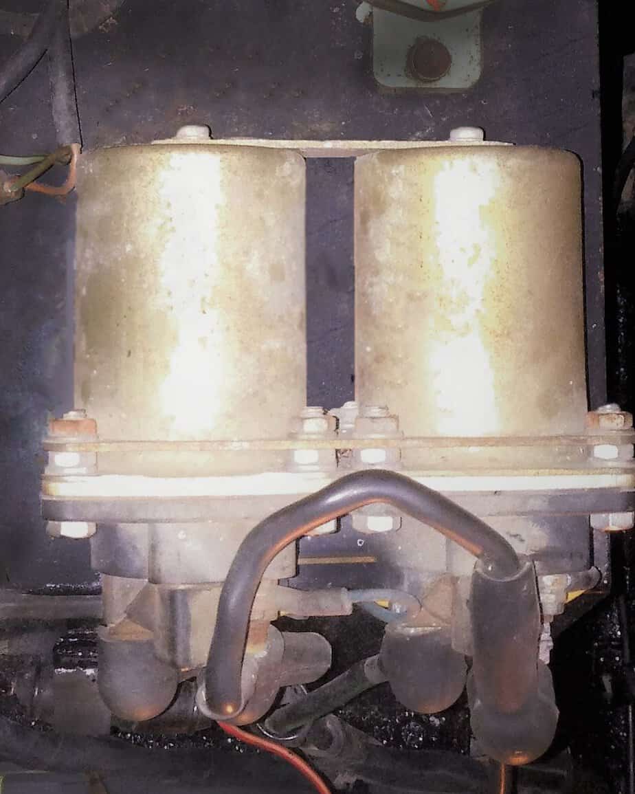
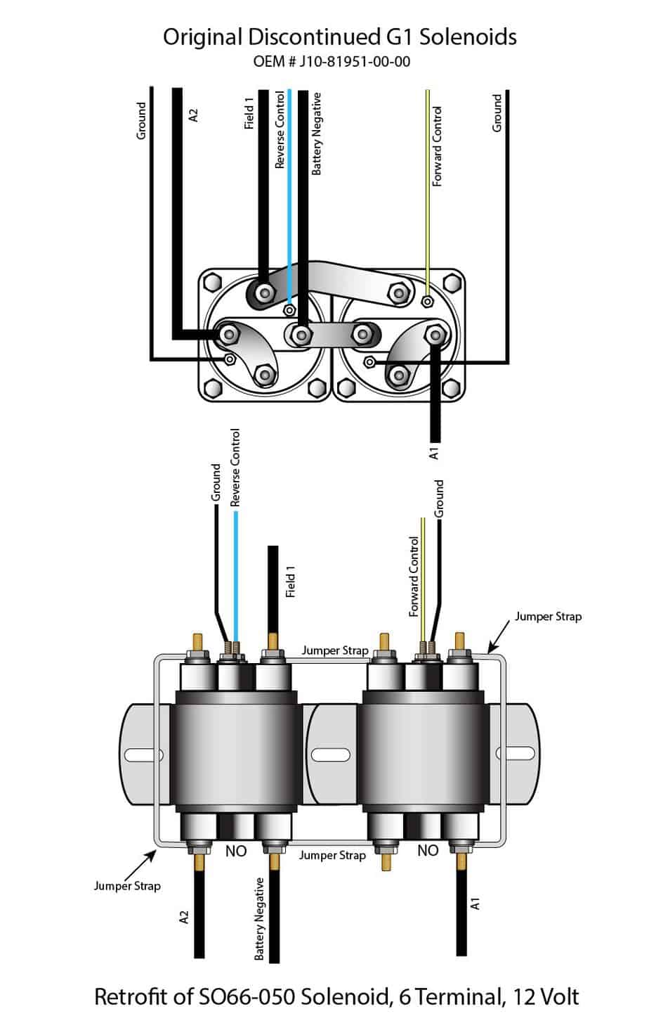
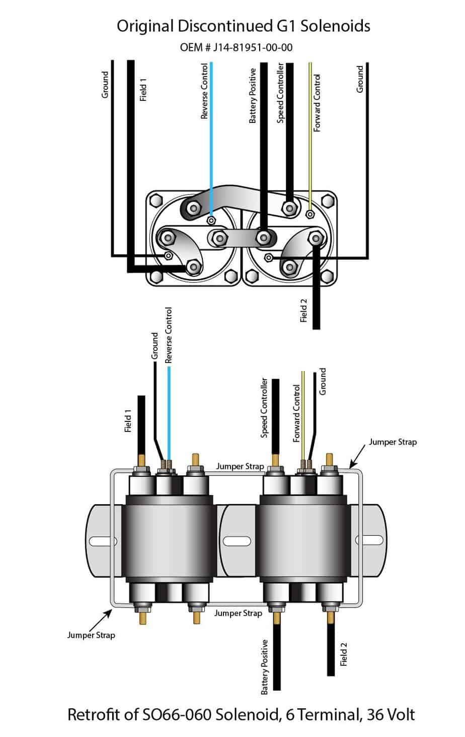
The first Generation Gas Carts had solenoids (or relays) that had all terminals on one end of the unit. These solenoids are no longer available and are replaced with a model with terminals on both ends. They are available at Vintage Golf Cart Parts. The replacement for the gas cart is a 12-volt model.
Retrofit for this solenoid is shown in the illustration below.
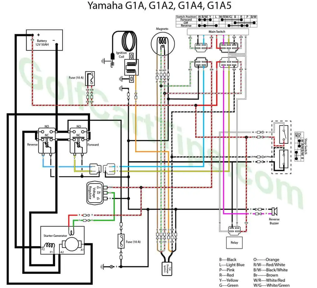
G1A,A2,A4,A5 Gas 1979-81, 1983-89
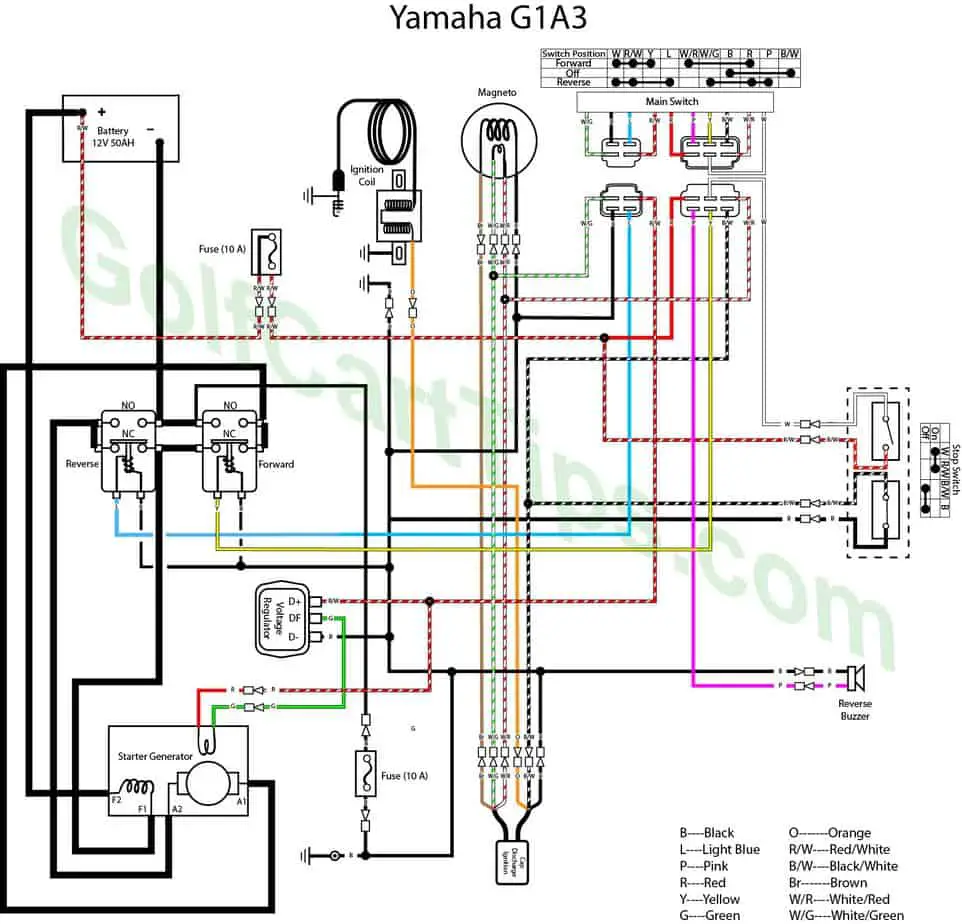
G1A3 Gas 1982
| Engine Will Not Turn Over | Battery is not charged | Test and recharge |
| Poor terminal connection | Clean and tighten | |
| Bad starter motor | Test, repair or replace | |
| Engine Turns Over, Will Not Start | Moisture on ignition wires and spark plug cap | Wipe wires and cap clean and dry |
| Faulty ignition cables | Replace any cracked or shorted cables | |
| Open or shorted primary ignition circuit | Trace primary ignition circuit and repair as necessary | |
| Faulty coil | Test and replace if necessary | |
| Dirt or water in fuel line or carburetor | Clean lines and carburetor. Replace filter | |
| Faulty fuel pump | Install new fuel pump | |
| Carburetor flooded or carburetor float setting incorrect | Adjust float level – check seats | |
| Loss of Power | Dirt or water in fuel line, carburetor or filter. | Clean lines, carburetor and replace filter |
| Incorrect ignition timing | Reset timing | |
| Dirty or incorrectly gapped spark plug | Clean plug and set gap – replace if neccessary | |
| Engine Stalls | Incorrect choke adjustment | Adjust choke |
| Idle speed set too low | Adjust idle speed on choke | |
| Incorrect carburetor float setting | Adjust float setting | |
| Faulty ignition wiring | Trace out and correct | |
| Dirty or incorrectly gapped spark | Clean plug and set gap | |
| Contaminates in fuel line or carburetor | Clean lines, carburetor and replace filter | |
| Faulty Coil | Check and replace | |
G1 Electric Carts
The first generation electric carts had solenoids (or relays) that had all terminals on one end of the unit. These solenoids are no longer available and are replaced with a model with terminals on both ends.
Below is the retrofit for replacing these with a contemporary solenoid.
G1E 1980-86
G1E 1980-86
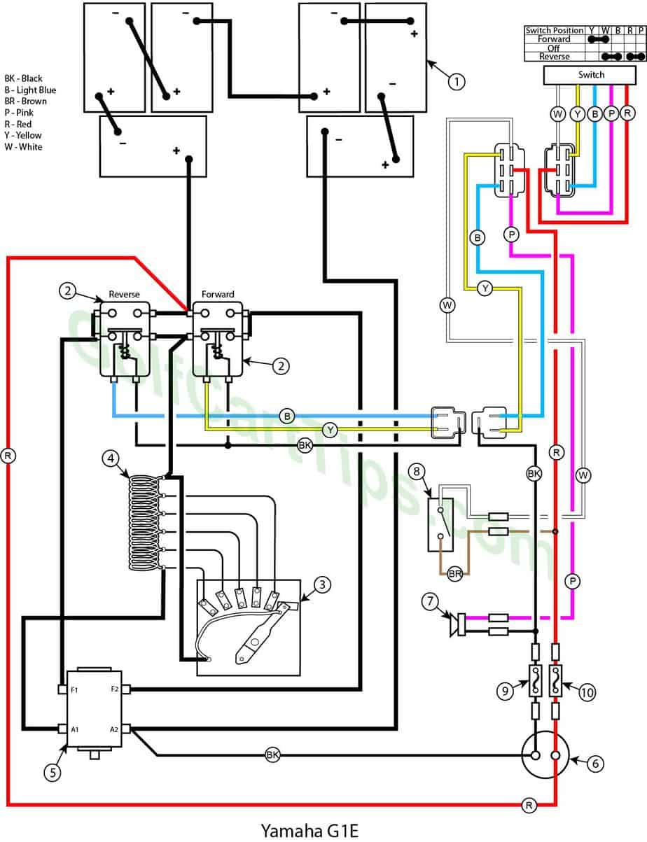
Item List
The wiper arm is at full rest and making contact with Contact Terminal #1.
- Batteries 6x6v
- Solenoid Relay
- Speed Controller
- Resistor Coil
- Traction Motor
- Charge Receptacle
- Back Up Buzzer
- Stop Switch (at pedal)
- 10 amp Fuse
- 10 amp Fuse
- Key switch – Off
- Speed Controller – At Contact #1
- Forward Solenoid – Not Energized
- Reverse Solenoid – Not Energized
- Voltage to Motor – None
- Voltage across A1 and A2 – None
- Voltage across F1 and F2 – None
- Stop Switch – In Open state
Power Flow Logic Diagram – Forward 1st Speed
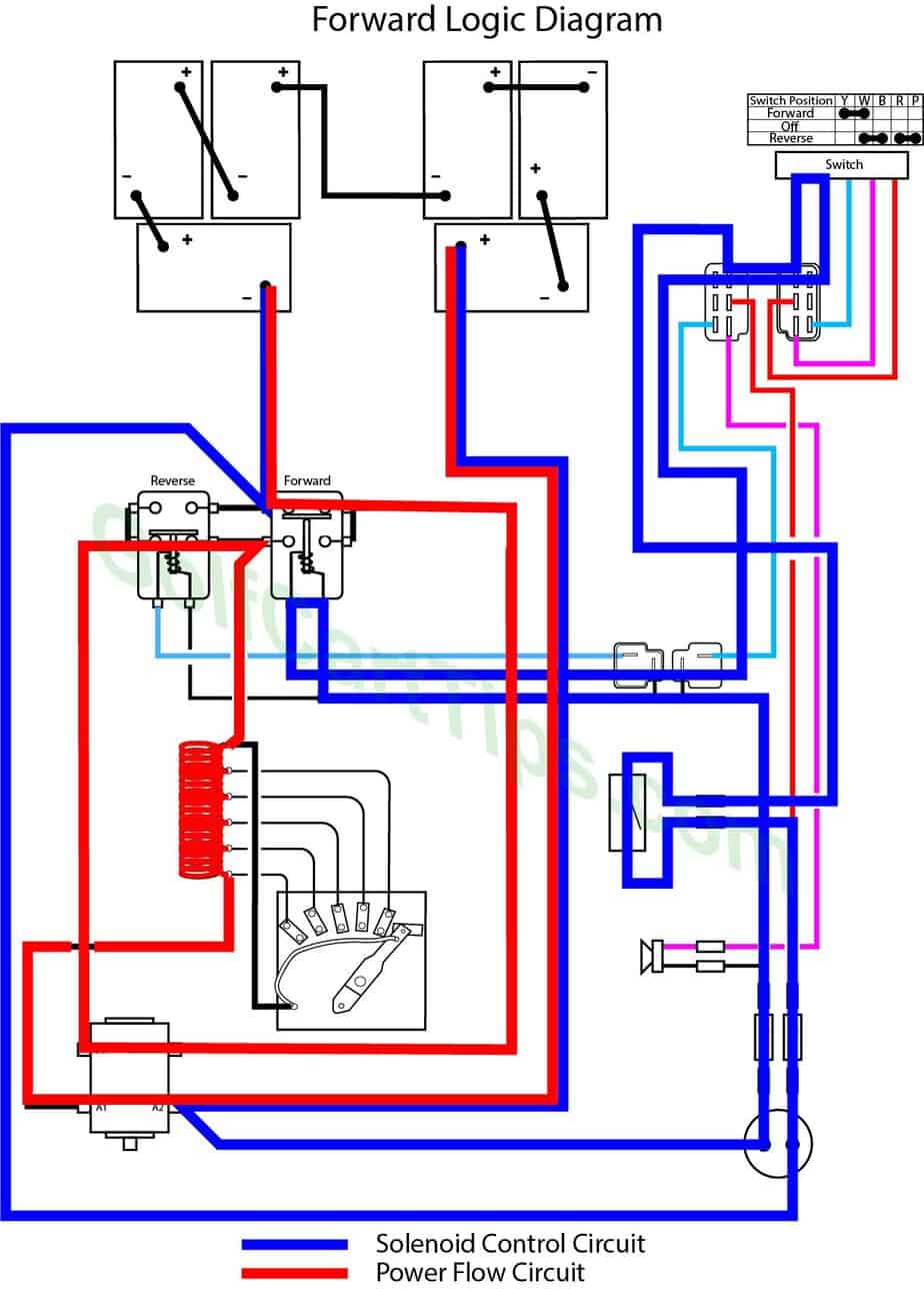
First Speed -the wiper arm is making contact with Contact Terminal #1 and pedal is slightly pressed.
- Key switch – Forward
- Speed Controller – At Contact #1
- Forward Solenoid – Energized
- Reverse Solenoid – Not Energized
- Voltage to Motor – Present
- Voltage across full resistor
- Stop Switch – In closed state
Power Flow Logic Diagram – Forward 2nd Speed
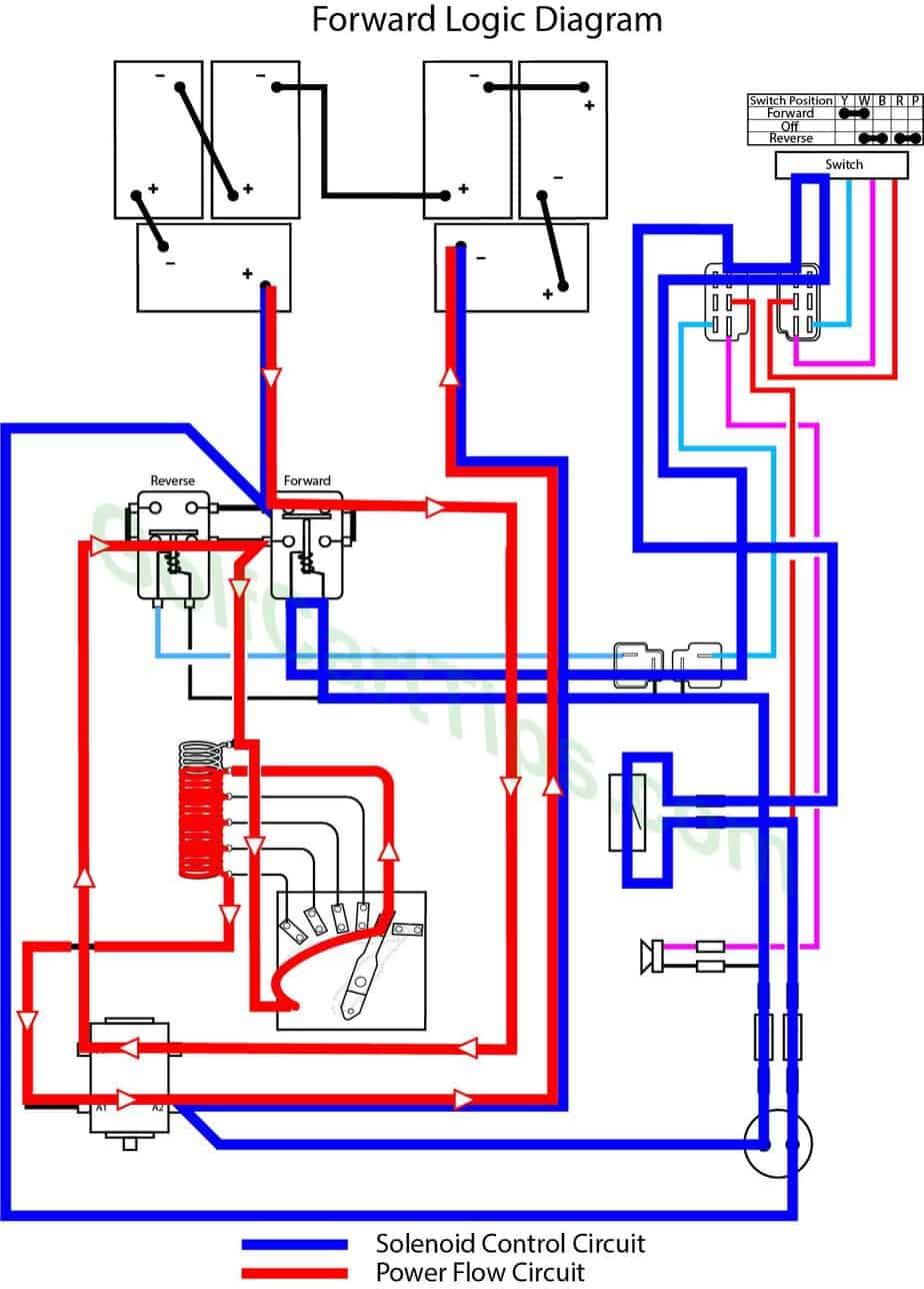
Second Speed – the wiper arm is making contact with Contact Terminal #2.
- Key switch – Forward
- Speed Controller – At Contact #2
- Forward Solenoid – Energized
- Reverse Solenoid – Not Energized
- Voltage to Motor – Present
- Voltage across 4/5 of resistor
- Stop Switch – In closed state
Power Flow Logic Diagram – Reverse 2nd Speed
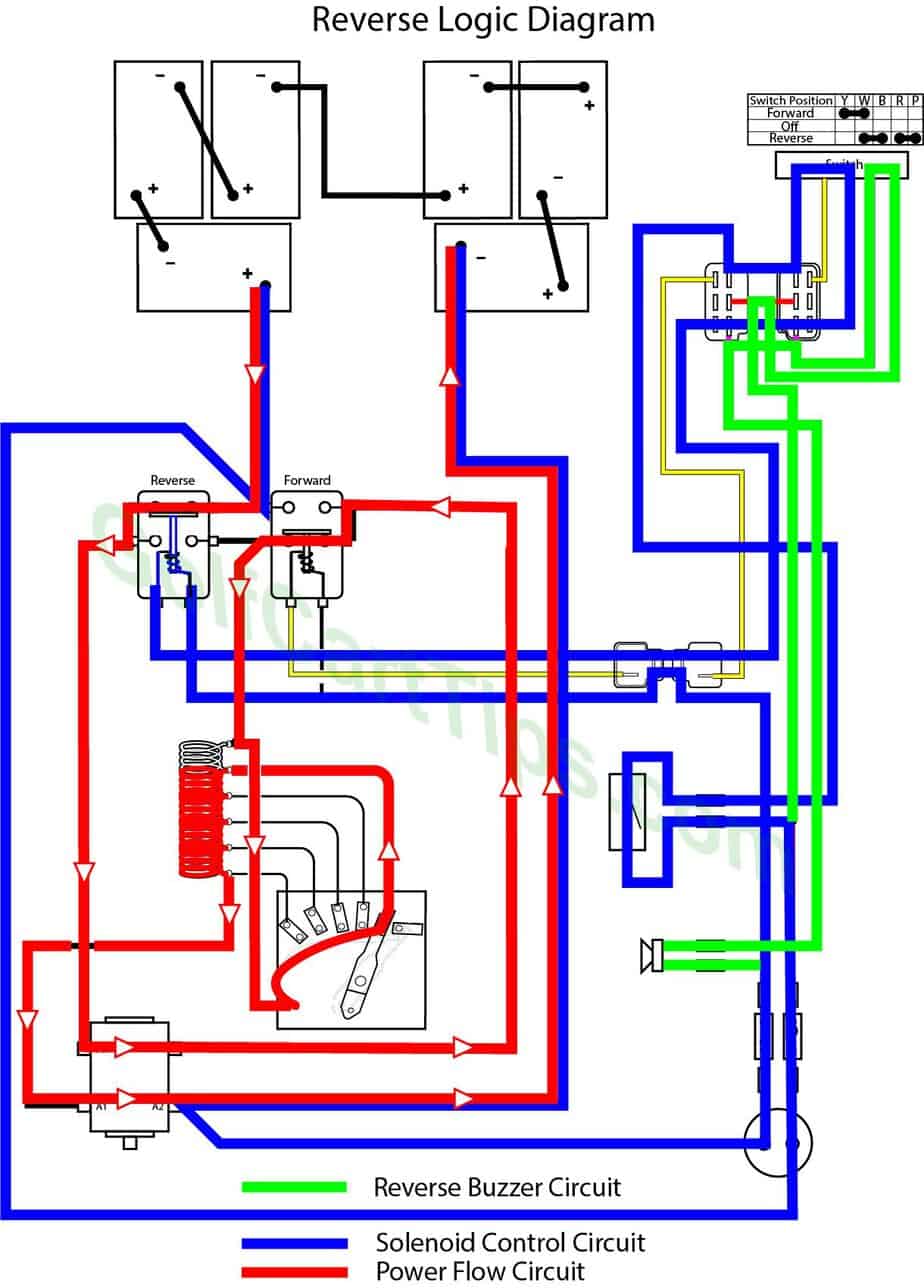
Second Speed Reverse – the wiper arm is making contact with Contact Terminal #2.
- Key switch – Reverse
- Speed Controller – At Contact #2
- Forward Solenoid – Not Energized
- Reverse Solenoid – Energized
- Voltage to Motor – F1 and F2 flow reversed
- Voltage across 4/5 of resistor
- Stop Switch – In closed state
- Reverse buzzer – Energized
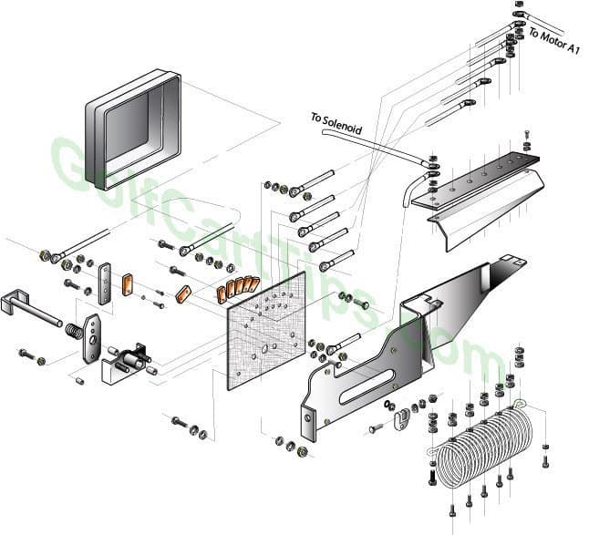
G1E Controller Exploded View
Troubleshooting Chart
| Motor Will Not Turn | Motor terminals are loose or corroded. | Tighten or clean tereminals |
| Brushes not contacting the commutator | Adjust | |
| Lead wires faulty | Check continuity, test, repair or replace | |
| Field coil broken | Repair or replace | |
| Armature coil broken | Repair or replace | |
| Motor Turns Slowly | Terminals loose and/or corroded | Check terminals, clean and tighten |
| Accelerator arm movement restricted | Adjust linkage | |
| Leads partially broken or loose | Check for loose wire strands, replace if defective, tighten connection | |
| Bearings Overheating Power | Bearings worn or low on grease | Replace |
| Bearings not installed correctly | Adjust bearings | |
| Noisy motor operation | Mounting bolts loose | Tighten mounting bolts |
| Bearing failure | Replace | |
| Bearings dirty | Replace | |
| Bearings run out of grease | Replace | |
| Dirt or foreign material in motor case | Clean motor | |
| Motor Vibration | Armature out of round | Replace |
| Motor mounting bolts loose | Retighten | |
Frequently Asked Questions
How do I know if my Yamaha G1’s solenoid is faulty?
Common signs include the golf cart failing to start, hearing a clicking sound without the engine turning over, or no sound at all when attempting to start. Testing the solenoid with a multimeter can confirm issues.
Can I replace the solenoid on my Yamaha G1 myself?
Yes, with basic mechanical skills, the right tools, and a proper wiring diagram, you can replace the solenoid. Ensure you disconnect the battery before starting any work to avoid electrical hazards.
What tools do I need for solenoid troubleshooting and replacement?
Essential tools include a multimeter for testing, wire strippers and crimpers for preparing and connecting wires, and basic hand tools like screwdrivers and wrenches for accessing and securing the solenoid.
How do I test the solenoid on my Yamaha G1 Golf Cart?
Using a multimeter, check for continuity between the solenoid’s terminals. A functioning solenoid should show continuity when activated (key turned or pedal pressed) and no continuity when inactive.
What should I do if my solenoid tests okay, but my golf cart still won’t start?
If the solenoid functions correctly, the issue may lie elsewhere in the electrical system. Check the battery, starter generator, and wiring connections for any signs of wear, damage, or loose connections.


Leave a Reply