Using Cushman Golfster Wiring Diagrams, troubleshooting the Cushman Golfster becomes a straightforward task, especially if you’re equipped with the necessary resources like exploded view drawings. Considering the advanced age of these vehicles, it’s quite common to come across instances where they’ve been poorly rewired. This situation underscores the absolute importance of having a comprehensive understanding of the original circuitry.
The Cushman brand designed two particularly well-known series of electric vehicles. This includes the 731 series meant for industrial use and the 732 series, synonymous with the iconic ‘Golfsters’. The history of these golf carts extends back to the years 1949 to 1954, a period during which they were simply known as ‘Golf Buggies’. They were primarily modified models of the original 60 series, built around the power of scooter engines. These models weren’t identified by the series number, but rather by individual serial numbers.
1954 heralded an essential shift in the design of these golf cart models. This is discernible through the introduction of hyphenated series numbers, which progressed in ascending order. For instance, the first model was labeled 732 – 7, while the succeeding year’s model was tagged 732 – 12. This system carried on for the subsequent models.
The turn of the decade in 1960 marked the abandonment of hyphenated series numbers. Instead, Cushman began identifying these electric golf cart and industrial vehicles by model numbers. Some examples include 878420 732 and 878417 731, among others. A comprehensive list of these model numbers is available for reference.
Interestingly, the original Golfster and Industrial vehicles were exclusively electric. It wasn’t until 1961 that Cushman ventured into producing a gasoline-powered Golfster boasting an impressive 18hp.
When dealing with cart wiring diagram troubleshooting, which is crucial in maintaining both Cushman and other brands like ezgo, club car, Yamaha, and even Harley Davidson, it is vital to understand the schematics and speed control system. Whether you are dealing with a standard golf cart or a 2023 model, understanding your golf cart wiring and potential issues, whether it’s done correctly or sometimes badly, can make a major difference in your cart’s functionality.
To conclude, the history of the Cushman electric vehicles, from being a simple Golf Buggy to the multipurpose electric Golfster, showcases its evolution. A deep understanding of its wiring and models can significantly aid in identifying issues and troubleshooting problems accurately.
Cushman Golfster Wiring Diagrams
Early Model Speed Switches

Wiring Diagram For 1954 Model 732-7 Golfster And 731-6 Industrial 24-Volt
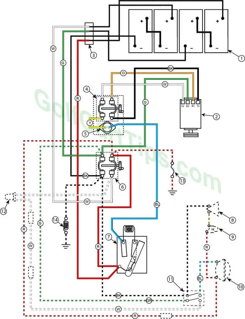
The 1954 Golfster and Industrial have two selector switches – one for two speeds, and one for forward and reverse. They have a two belt drive and no external charging plug.
- (4) 6-volt Batteries
- Motor
- Plug/ReceptacleBlocks
- Forward/Reverse Switch
- Circuit Breaker
- Speed Switch
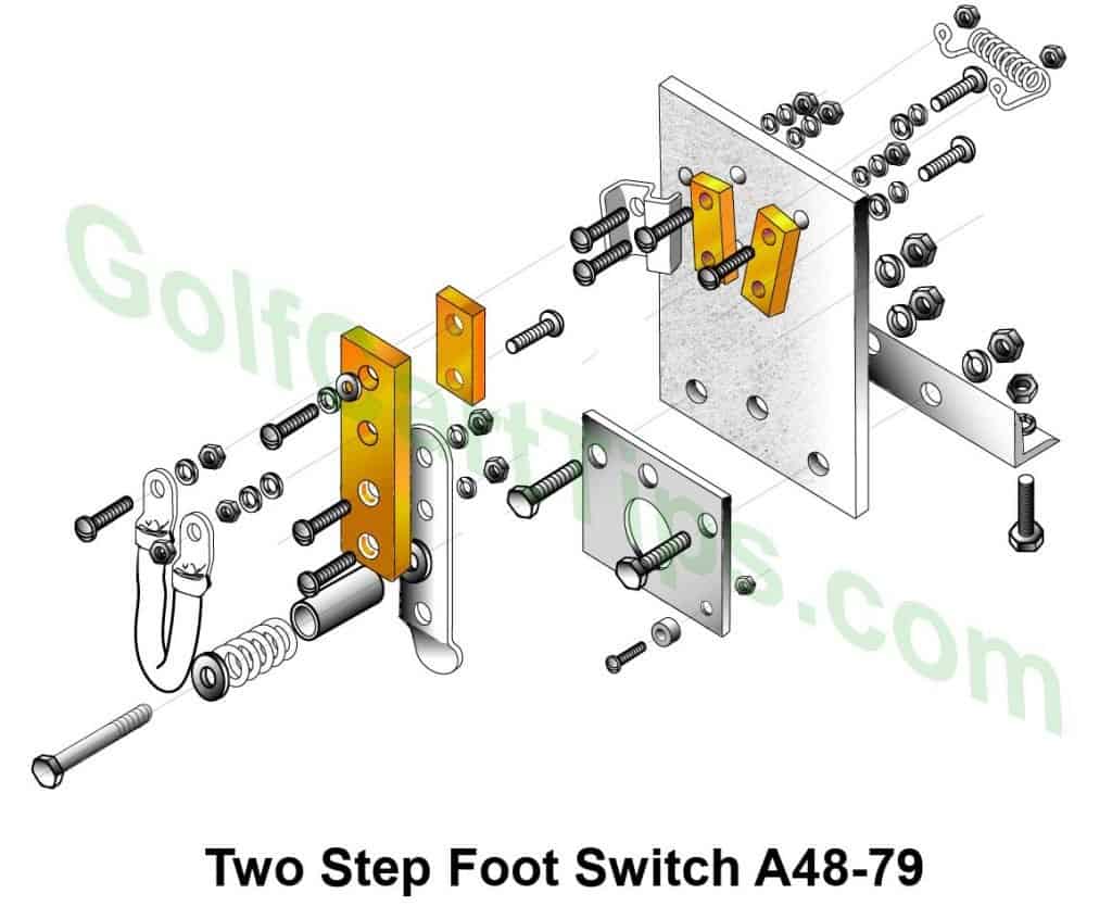
- Foot Switch – 2 Step Control
- Horn
- Horn Button
- Headlight
- Light Switch
- Tail Light
- Fuse
- Cigar Lighter
BK – Black
BL – Blue
G – Green
O – Orange
R – Red
Y – Yellow
W – White
Wiring Diagram For 1955 Model 732-12 Golfster And 731-11 Industrial 24 Volt

The 1955 Golfster and Industrial have one selector switch. They have a two belt drive and no external charging plug.
1. (4) 6-volt Batteries
2. Motor
3. Plug/Receptacle Blocks
4. Forward/Reverse Switch
5. Circuit Breaker
7. Foot Switch – 2 Step Control
8. Horn
9. Horn Button
10. Headlight
11. Light Switch
12. Tail Light
13. Fuse
14. Cigar Lighter
BK – Black
BL – Blue
G – Green
O – Orange
R – Red
Y – Yellow
W – White
Wiring Diagram For 1956 Model 732-19 Golfster And 731-18 Industrial 24-Volt
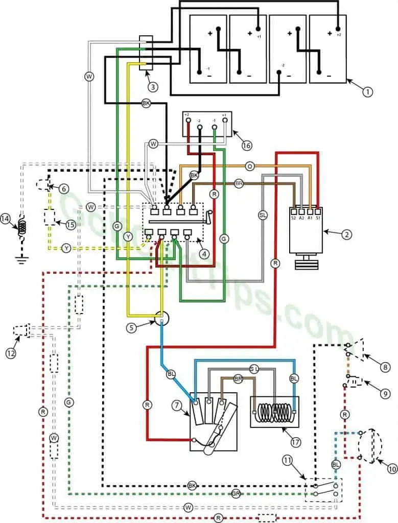
The 1956 Golfster and Industrial have one selector switch. They have a three belt drive and a four-prong external charging plug. The Cigar Lighter is discontinued.
1. (4) 6-volt Batteries
2. Motor
3. Plug/Receptacle Blocks
4.Forward/Reverse Switch
5. Circuit Breaker
6. Reverse Warning Light
7. Foot Switch – 3 Step Control
8. Horn
9. Horn Button
10. Headlight
11. Light Switch
12. Tail Light
15. Flasher
16. Charging Plug
17. Resistor
BK – Black
BL – Blue
BR – Brown
G – Green
O – Orange
R – Red
SL – Silver
Y – Yellow
W – White
Wiring Diagram For 1957 Model 732-34 Golfster And 731-33 Industrial 24-Volt
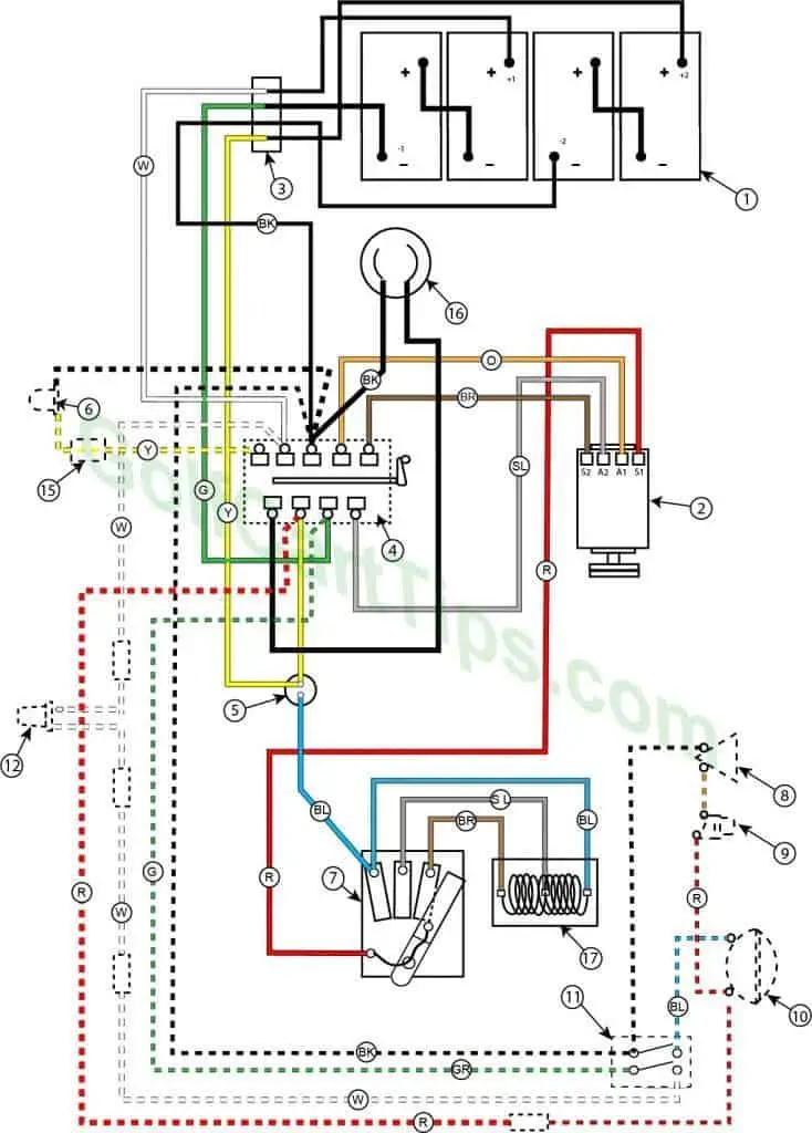
The 1957 Golfster and Industrial have one selector switch, now with a “Charge” setting. They have a three belt drive and a twist-lock external charging plug.
1. (4) 6-volt Batteries
2. Motor
3. Plug/Receptacle Blocks
4.Forward/Reverse Switch
5. Circuit Breaker
6. Reverse Warning Light
7. Foot Switch – 3 Step Control
8. Horn
9. Horn Button
10. Headlight
11. Light Switch
12. Tail Light
15. Flasher
16. Charging Plug
17. Resistor
BK – Black
BL – Blue
BR – Brown
G – Green
O – Orange
R – Red
SL – Silver
Y – Yellow
W – White
Wiring Diagram For 1957 Model 732-42 (24v) Golfster And 731-44 (24v) Industrial
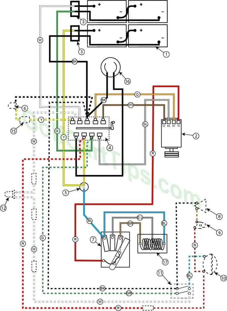
The 1957 Golfster and Industrial have one selector switch, now with a “Charge” setting. They have a three belt drive and a twist-lock external charging plug. It is now equipped with two battery racks.
. (4) 6-volt Batteries
2. Motor
3. Plug/Receptacle Blocks
4.Forward/Reverse Switch
5. Circuit Breaker
6. Reverse Warning Light
7. Foot Switch – 3 Step Control
8. Horn
9. Horn Button
10. Headlight
11. Light Switch
12. Tail Light
15. Flasher
16. Charging Plug
17. Resistor
BK – Black
BL – Blue
BR – Brown
G – Green
O – Orange
R – Red
SL – Silver
Y – Yellow
W – White
Wiring Diagram For 1957 Model 732-41 (36v) Golfster And 731-43 (36v) Industrial
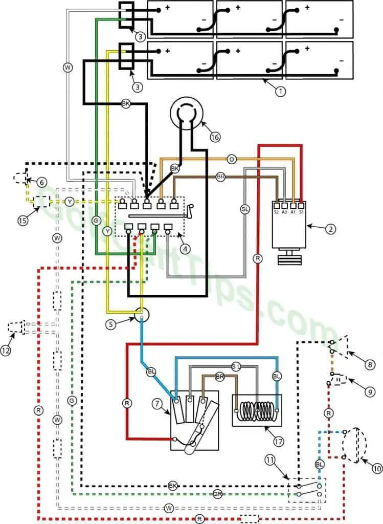
The 1957 36-volt Golfster and Industrial have one selector switch, now with a “Charge” setting. They have a three belt drive and a twist-lock external charging plug. It is now equipped with two battery racks.
1. (4) 6-volt Batteries
2. Motor
3. Plug/Receptacle Blocks
4.Forward/Reverse Switch
5. Circuit Breaker
6. Reverse Warning Light
7. Foot Switch – 3 Step Control
8. Horn
9. Horn Button
10. Headlight
11. Light Switch
12. Tail Light
15. Flasher
16. Charging Plug
17. Resistor
BK – Black
BL – Blue
BR – Brown
G – Green
O – Orange
R – Red
SL – Silver
Y – Yellow
W – White
Wiring Diagram For 1958 Model 732-73 (24v) Golfster And 732-71 (24v) Industrial

The 1958 24-volt Golfster and Industrial have one selector switch, now with a “Charge” setting. They have a three belt drive and a three-blade external charging plug. It is now equipped with two battery racks and a 3 blade Test Meter Plug.
1. (4) 6-volt Batteries
2. Motor
3. Plug/Receptacle Blocks
4.Forward/Reverse Switch
5. Circuit Breaker
6. Reverse Warning Light
7. Foot Switch – 3 Step Control
8. Horn
9. Horn Button
10. Headlight
11. Light Switch
12. Tail Light
15. Flasher
16. Charging Plug
17. Resistor
18. Test Meter Plug
BK – Black
BL – Blue
BR – Brown
G – Green
O – Orange
R – Red
SL – Silver
Y – Yellow
W – White
Wiring Diagram For 1958 Model 732-74 (36v) Golfster And 732-72 (36v) Industrial
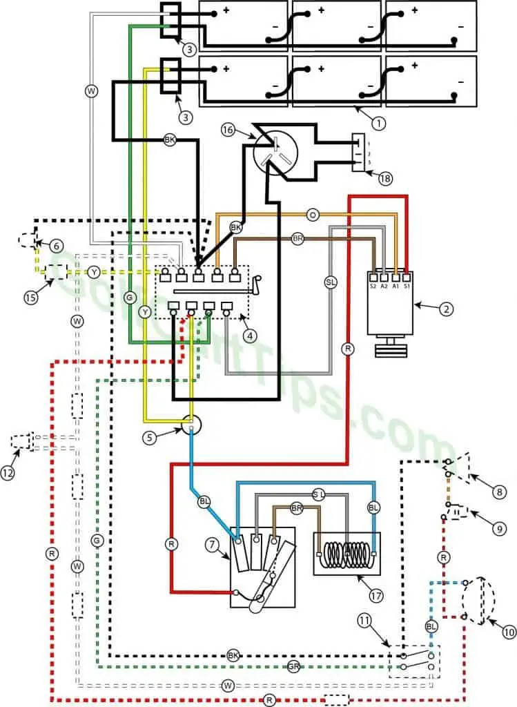
The 1958 36-volt Golfster and Industrial have one selector switch, now with a “Charge” setting. They have a three belt drive and a three-blade external charging plug. It is now equipped with two battery racks and a 3 blade Test Meter Plug.
1. (4) 6-volt Batteries
2. Motor
3. Plug/Receptacle Blocks
4.Forward/Reverse Switch
5. Circuit Breaker
6. Reverse Warning Light
7. Foot Switch – 3 Step Control
8. Horn
9. Horn Button
10. Headlight
11. Light Switch
12. Tail Light
15. Flasher
16. Charging Plug
17. Resistor
18. Test Meter Plug
BK – Black
BL – Blue
BR – Brown
G – Green
O – Orange
R – Red
SL – Silver
Y – Yellow
W – White



Leave a Reply