Club Car Golf Cart Wiring: Diagnose DS and Precedent Faults Step by Step
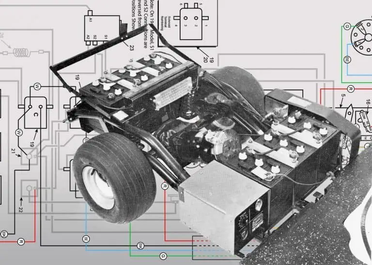
Club Car golf cart wiring problems follow recognizable patterns once you understand how the DS and Precedent electrical systems differ. The DS uses a series-wound DC motor with a Curtis or GE controller and a straightforward analog wiring layout that has changed relatively little from 1981 to 2000.
The Precedent added an OBC (onboard computer), a speed sensor on the rear axle, and a more complex control circuit that requires different diagnostic steps. This guide covers the most common wiring faults on both platforms in the order a mechanic would test them, with the correct voltage thresholds and continuity values for each test.
Last verified: Club Car DS 36V and 48V, Club Car Precedent IQ and IQ Plus | May 2026 | Wiring diagrams for DS models 1981-2002 are at the link in the DS section below
Key Takeaways
- The single most important preparation step before any Club Car golf cart wiring diagnosis is a full battery pack charge and a load test. A pack that reads 48V at rest but sags to 38V under load will produce symptoms that perfectly mimic a failed controller, a faulty solenoid, and a bad motor connection, all at the same time. Confirm the pack holds voltage under load before condemning any other component.
- On the Club Car Precedent, the OBC controls the charging circuit and the drive circuit through the IQ system. A Precedent that will not move, will not charge, or behaves erratically may have an OBC fault rather than a wiring fault. The OBC communicates fault codes through the battery charge indicator on the dash. Reading those codes before starting any wiring diagnosis saves significant time and prevents replacing good wiring components.
- Club Car DS controller test procedure: connect the negative multimeter probe to B- and the positive probe to B+. With the pedal released, reading should be near 0V. Press the pedal until the solenoid clicks in. Reading should jump to full pack voltage. Continue pressing. Reading should drop back toward 0V as the controller ramps up. If voltage goes from full pack to near zero with no motor movement, the fault is in the high-amperage drive circuit downstream of the controller, not the controller itself.
Club Car Golf Cart Wiring: DS vs Precedent System Differences
Understanding which platform is being diagnosed is essential before starting any Club Car golf cart wiring work. The DS and Precedent have fundamentally different electrical architectures, and a diagnostic step that applies to the DS does not necessarily apply to the Precedent.
The Club Car DS (1981 to present) uses a series-wound DC motor driven by a solid-state PWM controller. The DS electrical system consists of the battery pack, main fuse, key switch, forward/reverse switch, accelerator assembly, solenoid, controller, and motor. On 36V DS models, six 6V batteries are wired in series. On 48V DS models, six 8V batteries are wired in series.
The DS wiring color codes are consistent across production years and are documented in the Club Car DS service manual, available through Club Car’s owner support page. For complete year-by-year wiring diagrams covering 1981 to 2002, see the Club Car DS wiring diagrams guide.
The Club Car Precedent (2004 to present) uses the same series-wound DC motor as the DS on earlier models, with an IQ controller system that incorporates an OBC, a speed sensor, and a CAN bus communication network between components. The Precedent IQ Plus added regenerative braking and additional sensor feedback. The diagnostic approach for a Precedent must account for the OBC and speed sensor as potential fault sources before the traditional wiring components are tested.
| Component | Club Car DS | Club Car Precedent |
|---|---|---|
| Controller type | Curtis or GE solid-state PWM | Club Car IQ or IQ Plus controller |
| Controller amperage | 275A (36V) or 400A (48V) | 400A (standard) or 500A (IQ Plus) |
| OBC present | No | Yes, controls drive and charge circuits |
| Speed sensor | No | Yes, Hall effect sensor on rear axle |
| Fault code display | No built-in display | Battery charge indicator on dash |
| Solenoid | Standard SPST | Standard SPST (OBC-controlled) |
| Wire color standard | Club Car DS color code | Club Car Precedent color code |
Club Car Golf Cart Wiring: Tools Needed
A digital multimeter is the core diagnostic tool for all Club Car golf cart wiring work. It handles voltage testing at every point in the circuit, continuity testing for motor and switch verification, and resistance measurement for sensor checks. The multimeter must be rated for at least 60V DC measurement for 48V system work, and it should have a separate continuity function with an audible beep for quick switch and wiring checks.
A clamp meter that reads DC current is essential for checking whether the controller is delivering correct current to the motor under load, this is the definitive test for distinguishing a controller fault from a motor fault. Wire strippers, crimpers, and heat shrink tubing cover wiring repair work. A ball joint separator or connector tool is useful for disconnecting the multi-pin connectors on the Precedent IQ system without damaging the connector bodies.

- VERSATILE FUNCTIONALITY: Measures AC/DC voltage up to 600V, 10A DC current, 2MΩ resistance; additional features include …
- LEAD-ALERT PROTECTION: LEDs on the meter illuminate to indicate proper test lead placement, enhancing accuracy and safet…
- BACKLIT DISPLAY: LCD shows clear readings in low-light conditions for enhanced visibility

Club Car Golf Cart Wiring Fault 1: Cart Will Not Move
A Club Car that will not move when the key is turned and the pedal pressed has a fault somewhere in the drive circuit between the battery pack and the motor. Work through the following checks in order before replacing any component.
First, confirm the battery pack is fully charged and holds voltage under load. Measure pack voltage at the main positive and negative cables with the key on and the pedal pressed. If pack voltage drops significantly under load, the pack is the problem. Replace or rebalance the pack before further testing.
Second, confirm the key switch is passing voltage. With the key in the on position, measure voltage between the key switch output terminal and the cart’s main negative. Full pack voltage present means the key switch is functional. No voltage means the key switch has failed or the main fuse is blown. Check the main fuse continuity before condemning the key switch.
Third, test the solenoid. With the key on and the direction switch in Forward, measure voltage across the solenoid coil terminals (the two small terminals). If coil voltage is present and the solenoid does not click, the solenoid has failed. If coil voltage is absent, trace the coil circuit back to the forward/reverse switch and the key switch. On the Precedent, the OBC controls solenoid coil energization, if the OBC is not signaling the solenoid, the OBC is the fault rather than the solenoid.
Fourth, if the solenoid clicks but the cart does not move, bridge the solenoid’s two large main terminals with a heavy gauge jumper wire. If the motor runs, the solenoid main contact has failed. If the motor still does not run, the fault is downstream in the motor, motor connections, or the forward/reverse switch contacts.
Club Car Golf Cart Wiring Fault 2: Controller Voltage Test, DS Models
The Club Car DS controller voltage test is the definitive procedure for distinguishing a controller fault from a fault in the downstream high-amperage drive circuit. Perform this test only after confirming the battery pack is good, the solenoid is functioning, and the forward/reverse switch is passing voltage.
Connect the multimeter negative probe to the B- terminal on the controller and the positive probe to the B+ terminal. With the pedal released and the key on, the reading should be approximately 0V if the cart has not been operated in the past 15 to 30 minutes. Press the accelerator pedal slowly until the solenoid audibly clicks in. The multimeter reading should jump to full pack voltage at the moment the solenoid closes.
Continue pressing the pedal past the solenoid click point. The reading should begin dropping from full pack voltage toward 0V as the controller ramps up its PWM duty cycle to the motor. This voltage drop represents the controller reducing the effective voltage delivered to the motor through PWM switching, it is normal and correct behavior.
If the voltage starts at full pack voltage and drops correctly to near 0V but the motor does not move, the controller output circuit is functioning and the fault is in the high-amperage path downstream. Check the cable connections at the motor terminals, the condition of the forward/reverse switch contacts, and the motor itself. If the voltage does not drop from full pack when the pedal is pressed past the solenoid engagement point, the controller is not modulating output and has likely failed.
Club Car Golf Cart Wiring Fault 3: Motor Continuity Test
Before testing the motor, disconnect all four motor cables and label each one with the terminal it came from: A1, A2, F1, F2. Do not proceed without labeling, reconnecting cables to incorrect terminals on a series-wound DC motor reverses the motor’s direction of rotation or prevents it from running entirely.
Set the multimeter to continuity or low resistance mode. Test the following connections on the motor terminals themselves (not the cables, the terminals on the motor end):
- F1 to F2, continuity should be present. These are the field coil terminals. A healthy field coil reads 0.5 to 2 ohms resistance on most Club Car DS motors. Open circuit (no continuity) indicates a broken field winding.
- A1 to A2, continuity should be present through the armature and brushes. Resistance varies with brush position but should be well below 5 ohms. Open circuit indicates a broken armature winding or brushes not contacting the commutator.
- Any A terminal to any F terminal, continuity should NOT be present. Continuity between A and F terminals indicates an internal short in the motor that will cause erratic behavior or motor failure under load.
- Any terminal to the motor frame, continuity should NOT be present. Continuity between any terminal and the motor housing indicates an insulation failure that creates a ground fault in the wiring system.
A motor that passes all four checks is electrically sound. A motor that fails any check requires bench inspection or replacement. Do not condemn the motor based on these checks alone without first confirming the brushes are seated correctly, a brush that has popped out of its holder produces an open circuit between A1 and A2 that looks identical to a broken armature winding.
Club Car Golf Cart Wiring Fault 4: Forward/Reverse Switch
The forward/reverse switch on the Club Car DS reverses the current direction through the motor field coils, which reverses the motor’s direction of rotation. A switch fault produces symptoms ranging from the cart only operating in one direction, to no movement in either direction, to erratic behavior when switching between forward and reverse.
To test the forward/reverse switch, set the multimeter to continuity mode. With the switch in the Forward position, test for continuity across the contact pairs that should be closed in Forward according to the wiring diagram for your model year. With the switch in Reverse, the same contacts should be open and a different set should be closed. Contacts that do not change state when the switch is moved have failed mechanically, the contacts are either welded closed from arcing or the switch mechanism has broken internally.
On the Precedent, the forward/reverse switch is a micro switch assembly rather than the heavy-duty switch used on the DS. The Precedent’s switch sends a signal to the OBC rather than directly switching motor current. A failed micro switch on the Precedent produces an OBC fault code rather than the direct electrical symptom produced by a DS switch failure.
Club Car Golf Cart Wiring Fault 5: Precedent OBC and Speed Sensor
The OBC on the Club Car Precedent is the component that most frequently confuses owners who are familiar with DS diagnostics. The OBC controls both the drive circuit and the charging circuit. When it faults, it blocks both. A Precedent that will not move and will not charge simultaneously almost always has an OBC fault rather than simultaneous wiring failures in two separate circuits.
Reading OBC fault codes is the first step in any Precedent wiring diagnosis. With the key off, connect the charger. The battery charge indicator on the dash will display a series of blinks that correspond to a fault code table in the Club Car Precedent service manual. Count the blinks carefully, the pattern identifies the specific fault. Common Precedent fault codes include codes for low battery, speed sensor fault, motor current fault, and OBC communication fault.
The speed sensor is a Hall effect sensor on the rear axle that sends rotational pulses to the OBC. It is one of the most common Precedent-specific faults, often misdiagnosed as a motor or controller problem. The sensor itself costs $15 to $40 and replacement is straightforward.
To confirm a speed sensor fault: with the key on and the cart stationary, measure the sensor output signal voltage. A functioning Hall effect sensor outputs a pulsing signal of approximately 0V to 5V as the axle rotates. A failed sensor outputs a flat signal of constant 0V or constant 5V regardless of axle movement.
OBC replacement on the Precedent is the correct fix when the OBC itself is confirmed failed rather than a sensor or wiring fault. Aftermarket OBC replacements cost $80 to $150 and are a direct plug-in replacement on most Precedent years. Confirm part number compatibility with your specific Precedent year before ordering.
Club Car Golf Cart Wiring Fault 6: Solenoid Diagnosis
The solenoid is the single most commonly replaced component in Club Car DS and Precedent wiring repairs. It fails in two ways: the coil burns out (preventing the solenoid from energizing) or the main contact welds or wears out (preventing current from passing through the main circuit even when the coil energizes).
Test the solenoid coil with a multimeter on resistance mode. Disconnect the small coil wires from the solenoid. Measure resistance across the two coil terminals on the solenoid body. A healthy solenoid coil reads 1 to 5 ohms on most golf cart models. Open circuit (infinite resistance) means the coil has burned out. A coil that reads correctly but the solenoid body does not click when 12V or pack voltage is applied to the coil terminals indicates a mechanical fault in the plunger assembly.
Test the main contact by measuring resistance across the two large main terminals with the solenoid energized (coil voltage applied). A closed main contact should read under 0.1 ohms. A reading of 0.5 ohms or more indicates contact wear that causes a high-resistance connection under load. This manifests as a cart that operates at slow speed but loses power when the current demand increases on hills or with passengers. Replace the solenoid when main contact resistance exceeds 0.1 ohms.

- [Perfect Compatibility]: Golf cart pure copper coil 48V solenoid switch is designed specifically for Club Car DS (1995-u…
- [Replacement of OEM]: Club Car 4 terminal solenoid valve is compatible with OEM part numbers 101908701, 102774701, 5722,…
- [Rugged Construction]: 48V Club Car solenoid relay is manufactured with premium copper wire to ensure fast, reliable res…
Club Car Golf Cart Wiring Fault 7: Micro Switches and Pedal Assembly
The Club Car DS uses two micro switches in the accelerator pedal assembly: the run switch (sometimes called the safety switch) and the throttle switch. The run switch closes when the pedal is first depressed, completing the control circuit that allows the solenoid to energize. The throttle switch works with the potentiometer to signal pedal position to the controller. A failed run switch prevents the cart from starting. A failed throttle switch or potentiometer produces erratic speed behavior or a cart that accelerates immediately to full speed without gradual ramp-up.
To test a micro switch, use a multimeter in continuity mode. With the switch in its rest position, confirm the normally-open contacts are open and the normally-closed contacts are closed. Press the switch actuator manually. Confirm the contacts change state. A switch that does not change state when actuated has failed mechanically. Replace the individual switch rather than the full pedal assembly unless the potentiometer has also failed.
The potentiometer on the Club Car DS accelerator assembly is a variable resistor that produces a voltage signal proportional to pedal travel. Measure resistance across the wiper and one end terminal of the potentiometer while slowly moving the pedal through its full travel. Resistance should change smoothly and continuously from low to high with no dead spots or sudden jumps. A potentiometer with dead spots or abrupt resistance changes causes the cart to accelerate unevenly or cut out at specific pedal positions.
Club Car DS Wire Color Reference
The Club Car DS uses consistent wire color codes across most production years. The reference below covers the main circuit wires. Confirm against the specific wiring diagram for your model year when making repairs.
| Wire Color | Circuit | Notes |
|---|---|---|
| Red | Battery positive main | Heavy gauge, main positive cable |
| Black | Battery negative main | Heavy gauge, main negative cable |
| Yellow | Key switch output | Carries pack voltage when key is on |
| Blue | Forward direction signal | From F/R switch to controller |
| White | Reverse direction signal | From F/R switch to controller |
| Orange | Solenoid coil supply | From run switch to solenoid coil |
| Green | Speed signal / throttle | From potentiometer to controller |
| Purple | Run/safety switch circuit | Varies by year, confirm with diagram |
Always cross-reference color codes against the specific year diagram. Club Car made minor wiring changes across DS production years. For complete diagrams from 1981 through 2002, see the Club Car DS wiring diagrams guide. For charging system faults that cross over with wiring problems, see the 48 volt golf cart charger troubleshooting guide.
Club Car Golf Cart Wiring: Preventing Future Failures
Most Club Car golf cart wiring failures are caused by corrosion at connection points, vibration-induced wire chafing, and overloading the electrical system with accessories that draw more current than the wiring was designed for.
Inspect all connection points, battery terminals, solenoid terminals, motor terminals, and controller connectors, at least twice a year. Clean corrosion with a wire brush and baking soda solution, rinse with water, dry thoroughly, and apply dielectric grease or terminal protector spray before reconnecting. A high-resistance connection at any point in the main drive circuit causes voltage drop under load that produces motor performance problems indistinguishable from a failed component. The Battery University guide to lead-acid battery chemistry explains how corrosion at connection points causes electrochemical degradation that compounds over time.
Inspect the wiring harness routing at least annually for signs of chafing against frame edges, hot surfaces, or mechanical components. A wire that chafes through its insulation against the frame creates an intermittent ground fault that is among the most difficult wiring problems to trace. Secure any loose sections of harness with cable ties and add convoluted split loom conduit over sections that route near sharp edges or hot components.
Accessories that draw significant current, headlights, horns, radio systems, and USB charging ports, must be wired through a properly rated fuse to a dedicated circuit, not tapped into existing control wiring. A 20A accessory circuit tapped into a control wire rated for 5A will blow that circuit’s protective fuse, disabling the function it was meant to protect. For a comprehensive maintenance schedule that includes wiring inspection intervals, see the golf cart maintenance checklist.

- Easy to Use: Wire connectors can be connected with just a heat gun, no crimping tool or soldering machine is needed
- Waterproof and Insulating: Heat shrink tubing with low heat solder and hot melt adhesive can produce a perfect seal, whi…
- Wide Applications: Heat shrink butt connectors are ideal for marine, automotive, trailer and other outdoor applications

Frequently Asked Questions About Club Car Golf Cart Wiring
What are the most common Club Car golf cart wiring problems?
The most common Club Car DS wiring problems are solenoid main contact failure, corroded battery or motor terminals causing voltage drop under load, and failed forward/reverse switch contacts. On the Precedent, the most common wiring-related faults are OBC failures, speed sensor failures, and corroded IQ controller connectors. Battery pack issues produce symptoms that mimic all of these wiring faults, so confirming pack condition under load is always the first diagnostic step.
How do I reset the Club Car Precedent OBC?
With the key off, disconnect the negative main battery cable. Wait 60 seconds. Reconnect the negative cable. Turn the key on and observe the battery charge indicator for fault code blinks. If the fault condition has been corrected, the OBC should resume normal operation. If the fault code reappears, the underlying fault has not been resolved and OBC reset will not fix it. Do not use OBC reset as a substitute for diagnosing the root cause of the fault.
How do I test a micro switch on a Club Car?
Set a multimeter to continuity mode. With the switch at rest, test continuity across the normally-open terminals, there should be no continuity. Press the switch actuator manually. Continuity should now be present across the previously open terminals. Release the actuator. Continuity should clear. A switch that does not change state with actuator movement has failed mechanically and needs replacement. Micro switches for common Club Car applications cost $5 to $15 each.
What causes a Club Car DS to only run at one speed?
A Club Car DS that only runs at one speed regardless of pedal position has either a failed accelerator potentiometer, a failed controller speed input circuit, or a throttle wire fault. Test the potentiometer by measuring resistance across its wiper and one end terminal while slowly pressing the pedal. Resistance should change smoothly from low to high across the full pedal travel. A potentiometer that reads the same resistance at all pedal positions has failed. If the potentiometer is good, test the throttle signal voltage at the controller input terminal, it should vary with pedal position.
Why does my Club Car run slow on hills but fine on flat ground?
Reduced performance under load with normal performance on flat ground is the signature symptom of a high-resistance connection in the main drive circuit. The most common sources are a corroded battery terminal, a worn solenoid main contact, or corroded motor terminal connections.
Under light load the resistance loss is small enough to be unnoticeable. Under heavy load the same resistance causes significant voltage drop that reduces motor output. Test each main circuit connection by measuring voltage drop across each connection point with a multimeter while the cart climbs a hill.
About the Author
Chuck Wilson spent decades as a golf cart and small vehicle mechanic before retiring. His shop work covered Club Car, EZGO, and Yamaha platforms across gas and electric drivetrains. He runs GolfCartTips.com in retirement, writing about repairs and maintenance based on jobs he has actually done, not manufacturer talking points. If a procedure is on this site, it has been performed on a real cart.
Last verified on: Club Car DS 36V (1995-2000), Club Car DS 48V (2000-2010), Club Car Precedent IQ 48V (2004-2015). Controller voltage test procedure confirmed against Club Car DS and Precedent service manuals. Motor continuity values cross-referenced against Club Car factory specifications.